Posts

Showing posts with the label Toy

Toy Siren Circuit Diagram
Image
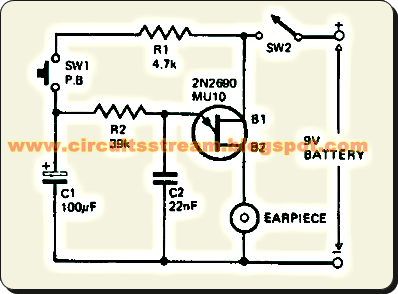
This simple Toy Siren circuit for hobbyist and student who game liker, this is a very simple Toy Siren circuit,  This Toy Siren circuit can be built small enough to frt inside a toy. The Toy Siren circuit consists of a relaxation oscillator utilizing one uni-junction transistor (2N2646, MU10, TIS43). R2 and C2 determine the frequency of the tone.   Simple Toy Siren Circuit Diagram Pushing the button, SW1 charges up the capacitor and the potential at the junction of R2 and C2 rises, causing an upswing in the frequency of oscillation. On releasing the push-button the charge on C2 will drop slowly with a proportional reduction in the frequency of oscillation. Manual operation of the button at intervals of approximately 2 seconds will produce a siren sound. Sourced By: Circuitsstream

Interactive Toy Traffic Lights

Image
This toy traffic signal uses a single low-cost hex Schmitt-trigger inverter IC (IC1a-IC1f) to directly drive three coloured LEDs (red, green and amber). At switch-on, the circuit lights the red signal for 30s, then shows green for 6s, then amber for 3s. It then repeats the sequence. Interaction is provided by pushbutton S1 which abbreviates the red period to a further 3s only, if it is pressed while the red signal is showing. Sequencing of the three LEDs is controlled by inverters IC1c, IC1d & IC1e, while the electrolytic capacitors at the inverter outputs and their associated 2.7MO resistors determine how long each LED stays on. Diodes D3, D4 & D5 discharge the timing capacitors for the next two LEDs in the sequence while the current LED is on. Note also the 10kO resistor at the input of each inverter. These protect the inverter inputs from being damaged by the negative voltage produced when the previous output goes low while its timing capacitor is fully charged. The circuit ...