Posts

Showing posts with the label For

Power Diode For Solar Power Systems

Image
Apart from the sun, solar power systems cannot work without a reflow protection diode between the solar panel and the energy store. When current flows into the store, there is a potential drop across the diode which must be written off as a loss in energy. In the case of a Schottky diode, this is not less than 0.28 V at nominal current levels, but will rise with higher ones. It is clear that it is advantageous to keep the energy loss as small as possible and this may be achieved with external circuitry as shown in the diagram. The circuit is essentially an electronic switch consisting of a high precision operational amplifier, IC1a, a Type OP295 from Analog Devices, and a MOSFET, T1. This arrangement has the advantages over a Schottky diode that it has a lower threshold voltage and the lost energy is not dissipated as heat so that only a small heat sink is needed. When the potential at the non-inverting input of the op amp, which is configured as a comparator, rises above that at the i...

Fuel Reserve Indicator For Vehicles

Image
Here is a simple circuit for monitoring the fuel level in vehicles. It gives an audiovisual indication when the fuel level drops alarmingly below the reserve level, helping you to avoid running out of petrol on the way. Nowadays vehicles come with a dash-mounted fuel gauge meter that indicates the fuel levels on an analogue display. The ‘reserve’ level is indicated by a red marking in some vehicles, but the needle movement through the red marking may be confusing and not precise. This circuit monitors the fuel tank below the reserve level and warns through LED indicators and audible beeps when the danger level is approaching. Circuit diagram : Fuel Reserve Indicator For Vehicles Circuit Diagram The fuel sensor system consists of a tank-mounted float sensor and a current meter (fuel meter), which are connected in series. The float-driven sensor attached to an internal rheostat offers high resistance when the tank is empty. When the tank is full, the resistance decreases, allowing m...

Low pass filter for subwoofer

Image
Description. Many low pass filter circuits for subwoofer are given here and this is just another one. The circuit given here is based on the opamp TL062 from ST Micro electronics. TL062 is a dual high input impedance J-FET opamp which has very low power consumption and high slew rate. The opamp has excellent audio characteristics and is very suitable for this circuit. Out of the two opamps inside TLC062, first one is wired as the mixer cum pre amplifier stage. The left and right channel are connected to the inverting input of IC1a for mixing. The gain of first stage can be adjusted using POT R3.The output of the first stage is connected to the input of second stage through the filter network comprising of components R5,R6,R7,R8,C4 and C5. The second opamp (IC1b) serves as a buffer and the filtered output is available at the pin 7 of the TLC062.   Circuit diagram.   Power supply for the circuit. Notes. Assemble the circuit on a good quality PCB. The circuit can be powered from...

ICL7107 Voltmeter Circuit for Digital Panel Meter

Image
Here is an ICL7107 voltmeter is used as a display panel meter from a capacitor bank. Display compact designed to fit its placement as a display meter, which is very suitable to use seven segments LED. If you prefer using the LCD display, it is recommended to use the ICL7106. The voltmeter circuit uses a symmetric voltage + /-5V as power supply. -5V voltage can be easily generated from ICL7660 IC with +5 V supply. Digital voltmeter circuit supports a display 31/2 digits. The measurement range is of course the voltage divider at the input signal (pin 30,31) of the IC’s from. Voltmeter Panel Display ICL7107 Voltmeter Circuit Diagram Below is the ICl7107 digital voltmeter circuit diagram , there are two pieces of IC 7107 serves as an analog to digital converter, and ICl7660 to provide a negative voltage-5V from +5 V power supply 7 Segments display serves to display results from a voltage measurement. Pin 30,31 of the IC is the input voltage to be measured with the option Low/High inp...

Auto Sound Systems for the Budget Minded

Despite popular belief, it is quite possible to get a great quality auto sound system even if you are operating on a limited budget. I completely understand your skeptical glances and the comments and grumbles that being on a budget means different things to different people. I can tell you without a doubt that you can get a really nice sound system for your car, truck, or SUV even if your budget is less then $300. There are several things you can do as a savvy consumer that will help drive the price of the wonderful sound you seek to a bare minimum if you use a few tips, tricks, and techniques, in order to do so. First of all, the competition in this market is fairly fierce. As a result of that you will find that prices tend to be pretty competitive from one shop to another and that your best bargains are usually going to be found online. Search around online and find the absolute best bargain you can find on the auto sound system of your dreams. Once you've found the lowest onlin...

Simple and extensible microprocessor driver for robots

Image
I will start from saying that the board could be replaced by any Arduino plus some(s) its motor driver shield(s). So why I made it you may ask? Well, while I made this tiny tank-robot model presented on below pictures, I wanted to make at least some things by myself, and decide what I need and how I need it instead of only buying prefabricated stuff. [ ]

Power Supply for Walkie Talkies

Image
Here is a simple power supply circuit that can be used for citizenband and VHF walkie-talkies of power rating up to 10 watts. The circuit uses a step-down transformer, followed by bridge rectifier, filter, regulator, and current booster stages. A pnp power transistor is added to the circuit to increase its current sourcing capabilities. Regulator 7812 can support around 100 mA current. When the current flowing through R1 nears 100mA value, the voltage (>0.65V) across the emitter-base junction makes transistor T1 to conduct and provide a path for additional current. Circuit diagram : Power Supply for Walkie Talkies Circuit Diagram The circuit can source around one ampere of current at 12+1.4 volts=13.4 volts. Both the regulator IC and the power transistor must be mounted on heat sinks.

Compact simple Fm transmitter for 1km

Image
Description This one is a high power long range (use yagi antenna)  FM Transmitter  that provides very good frequency stability in about 1km range and very good microphone sensitivity. It can be used inside guitars, as a part of remote control systems or in other similar applications. The features said above are achieved by including an RF amplifier stage with 10dB gain and AF preamplifier stage to boost the modulation. Description The circuit construction is simple. L1 is integrated into the PCB with 3.25 turns. Transistors are not critical. The BC547s can be replaced with any small signal NPN type transistor and BC557 is a general purpose PNP transistor so it can also be replaced easily. The power consumption is low. The finished circuit draws about 30mA. A single 9V battery is ample to power the FM wireless microphone. The PCB file is given in the download section of the project page. You should check Harry's page for more detailed information about the components, PCB modi...

Oil Temperature Gauge for 125 cc Scooter

Image
Lots of Far-Eastern scooters are fitted with GY6 engines. These already elderly units are sturdy and economical, but if you want to  “push” the power a bit (so called ‘Racing’  kits, better handling of the advance, etc.), you soon find yourself faced with the problem  of the engine temperature, and it becomes essential to f it a heat sink (of ten wrongly  referred to as a ‘radiator’) on the oil circuit. Even so, in these circumstances, it’s more than reassuring for the user to have a constant clear indication of the oil temperature. Here are the specifications we set for the temperature gauge we wanted to build:  Oil Temperature Gauge Circuit Diagram : no moving parts (so not meter movement), as scooters vibrate a lot!; as cheap as possible (around £12); robust measuring transducer (avoid NTC thermistors and other ‘exotic’ sensors); temperature range 50–140 °C. (122 – 291 °F); audible and visual warning in case of dangerous temperature; compact; waterproof. Let...

FM adaptor circuit for car stereo

Image
Description. W ith this compact FM adaptor circuit plugged into the audio out of your cassete player or i Pod out put,you can listen your favorite music on your car stereo.This circuit is very useful if your car stereo doesnot have an auxillary in socket.The circuit is nothing buy  an short range  FM transimitter. The FM transmitter circuit is based on low power NPN transistor 2N2222.The tank circuit consisting of L1 & C1 producess the necessary oscillations at the collector of Q1.The capacitance C4 , resistance R3 & R4  performs the function of mixing the stereo out put from theaudio player or i-Pod.The emitter resistance R2 provides sufficient stability to the circuit.It also limits the collector current to increse the battery life. Circuit diagram with Parts list. Notes. Use a 28SWG , 10 cm insulated copper wire as antenna. For L1.make 8 turns of 20 SWG insulated copper wire on a 5mm dia plastic former. Power the circuit from a 3V battery. Assemble the circ...

Build a 60 dB Range Compressor For Audio

Image
A 60-dB Range Compressor circuit shown in the schematic diagram below can produce consistent output of 1.4V P-P over entire 60dB range that is very useful for audio level/volume stabilization.  As the main components, this circuit uses a 741 opamp and JFET. With input range of 20mV to 2oV, this circuit has delay time of 0.4s (decay time)  and response time of 1.2ms (attack time). The JFET is used as  voltage-controlled resistor in peak-detecting control loop of 741 opamp. Here is the schematic diagram of the circuit.  A 60-dB Range Compressor schematic diagram

Color Codes for Resistors

Image
  If 3rd band is gold, Divide by 10 If 3rd band is silver, Divide by 100 (to get 0.22ohms etc)  

53 dB Stereo Preamplifier for Tape or Phonographs

Image
With the circuit shown in the following schematic diagram, both channels of this stereo preamp is constructed using  RCA CA3052 quad AC amplifier.  this pre-amplifier circuit is featured with tone control (bass – treble). Make a similar circuit to complete the other channel, since the circuit for left and right channel are similar. To be high-fidelity, total harmonic distortion should be kept minimum, this circuit gives less than 0.3% distortion level at  at 1-kHz testing signal with 1-V amplitude.   Gain or amplification at 1 kHz is 47 dB,  and the tone control will curve the response with 11.5-dB boost at 100 Hz and 10 kHz at maximum bass and treble boost.  For minimum bass and treble knob position,  the attenuation will be 10dB  at 100 Hz  and 9dB at 10kHz. This circuit is operated by a single ended supply for wider range environment. Inputs can be from tape recorders pickup or magnetic-cartridge phonographs. 53 dB Stereo Preamplifier...

A Doorbell for the Deaf Circuit Diagram

Image
This circuit provides a delayed visual indication when a door bell switch is pressed. In addition, a DPDT switch can be moved from within the house which will light a lamp in the door bell switch. The lamp can illuminate the words "Please Wait" for anyone with walking difficulties. A Doorbell for the Deaf Circuit Diagram : Notes : The circuit uses standard 2 wire doorbell cable or loudspeaker wire. In parallel with the doorbell switch, S1, is a 1N4001 diode and a 12 volt 60mA bulb. The bulb is optional, it may be useful for anyone who is slow to answer the door, all you need to do is flick a switch inside the house, and the bulb will illuminate a label saying Please Wait inside the doorbell switch or close to it. The double pole double throw switch sends the doorbell supply to the lamp, the 22 ohm resistor is there to reduce current flow, should the doorbell switch, S1 be pressed while the lamp is on. The resistor needs to be rated 10 watts, the 0.5 Amp fuse protects against...

Headphone amplifier IC for portable equipment

General Description: AN7531SA is an audio signal processing IC in which bass boost amplifiers, ALC circuit and beep circuit are built in the headphone amplifiers for use in portable equipment. Its headphone output block is using the center amplifier method which eliminates the need for coupling capacitor so that the circuit is most suitable for rationalization of audio circuit.  Circuit diagram:  See in datasheet

Simple Knight Rider lights Circuit for model cars

Image
This simple circuit drives 6 LEDs in 'Knight Rider scanner mode'. Power consumption depends mainly on the type of LEDs used if you use a 7555 (555 CMOS version). Simple Knight Rider lights Circuit Diagram Note That V DD and GND for the ICs are not shown in the circuit drawing. Pin-outs: (7)555 4017 1 GND 1 Q5 9 Q8 2 TRIGGER 2 Q1 10 Q4 3 OUTPUT 3 Q0 11 Q9 4 RESET 4 Q2 12 CO 5 CONTROL VOLTAGE 5 Q6 13 NOT ENABLE 6 THRESHOLD 6 Q7 14 CLK 7 DISCHARGE 7 Q3 15 RESET 8 V DD 8 GND 16 V DD

SSB Add On For AM Receivers

Image
Given favourable radio wave propagation, the shortwave and radio amateur band are chock-a-block with SSB (single-sideband) transmissions, which no matter what language they’re in, will fail to produce intelligible speech on an AM radio. SSB is transmitted without a carrier wave. To demodulate an SSB signal (i.e. turn it into intelligible speech) it is necessary to use a locally generated carrier at the receiver side. As most inexpensive SW/MW/LW portable radios (and quite a few more expensive general coverage receivers) still use plain old 455 kHz for the intermediate frequency (IF), adding SSB amounts to no more than allowing the radio’s IF to pick up a reasonably strong 455-kHz signal and let the existing AM demodulator do the work. Circuit diagram: The system is called BFO for ‘beat frequency oscillator’. The heart of the circuit is a 455-kHz ceramic resonator or crystal, X1. The resonator is used in a CMOS oscillator circuit supplying an RF output level of 5 Vpp. which is radiated ...

Auto LED Taillight for a Bike

Image
This is a circuit for automatically switching off and LED taillight for a bike. The backlight turns on by movement (in the dark). After about 20 minutes of inactivity, the backlight is switched off again. So you cannot forget to turn off the backlight so that you are less likely surprised by batteries.  Auto LED Taillight Circuit Diagram S1 is a motion switch. When the switch closes C1 is charged. Therefore FET switches T1 and burn the LED. T1 can however only enabled when R3 is sufficiently high resistance, or when it is dark. R1 C1 discharge slowly so that after about 20 minutes the FET turns off and the LED goes out. The circuit may be built into the housing of a rear light on the battery that is inexpensive to buy in the market. That way you already have a beautiful body. Parts List:      R1 = 2.2 MΩ      R2 = 2,2 kohm      R3 = LDR      R4 = 220 K?      R5 = 22 K?   ...

Circuit modifications for operating 150 LEDs

Image
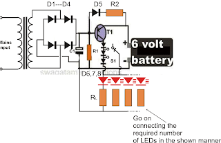
Parts List R1 = 220 Ohms, 1/2 watt R2 = 100Ohms, 2 watts, RL = All 22 Ohms, 1/4 watt, C1 = 100uF/25V, D1,2,3,4,6,7,8 = 1N5408, D5 = 1N4007 T1 = AD149 or similar, Transformer = 0-6V, 500mA

Lambda Probe Readout For Carburetor Tuning

Image
A lambda probe (or oxygen sensor) can be found on the exhaust system of most cars running on unleaded fuel. Having reached its normal operating temperature (of about 600 degrees Celsius!) the lambda probe supplies an output voltage proportional to the amount of residual oxygen measured in the exhaust gas. This information is indicative of, among others, the air/fuel ratio supplied by the carburetor(s) and hence the combustion efficiency. In modern car (and motorcycle) engines, this information is used to (electronically) adjust engine parameters like ignition timing and fuel injection. The indicator described here is intended for permanent installation on a motorcycle of which the air/fuel ratio needed to be watched, with the obvious aim engine power tuning after fitting a different set of carburetors. Apart from this obvious technical use the unit’s bright LEDs will no doubt attract the attention of curious motorcyclists. At the local junkyard a single-wire lambda probe may be salvage...