Posts

Showing posts with the label Preamplifier

A Simple MD Catridge Preamplifier

Image
Phonographs are gradually becoming a rarity. Most of them have had to yield to more advanced systems, such as CD players and recorders or (portable) MiniDisc player/recorders. This trend is recognized by manufacturers of audio installations, which means that the traditional phono input is missing on increasingly more systems. Hi-fi enthusiasts who want make digital versions of their existing collections of phonograph records on a CD or MD, discover that it is no longer possible to connect a phonograph to the system. Circuit diagram : A Simple MD Catridge Preamplifier Circuit Diagram However, with a limited amount of circuitry, it is possible to adapt the line input of a modern amplifier or recorder so that it can handle the low-level signals generated by the magnetodynamic cartridge of a phonograph. Of course, the circuit has to provide the well-known RIAA correction that must be used with these cartridges. The preamplifier shown here performs the job using only one opamp, four resisto...

53 dB Stereo Preamplifier for Tape or Phonographs

Image
With the circuit shown in the following schematic diagram, both channels of this stereo preamp is constructed using  RCA CA3052 quad AC amplifier.  this pre-amplifier circuit is featured with tone control (bass – treble). Make a similar circuit to complete the other channel, since the circuit for left and right channel are similar. To be high-fidelity, total harmonic distortion should be kept minimum, this circuit gives less than 0.3% distortion level at  at 1-kHz testing signal with 1-V amplitude.   Gain or amplification at 1 kHz is 47 dB,  and the tone control will curve the response with 11.5-dB boost at 100 Hz and 10 kHz at maximum bass and treble boost.  For minimum bass and treble knob position,  the attenuation will be 10dB  at 100 Hz  and 9dB at 10kHz. This circuit is operated by a single ended supply for wider range environment. Inputs can be from tape recorders pickup or magnetic-cartridge phonographs. 53 dB Stereo Preamplifier...

Preamplifier and Equalizer TDA1523

Image
FEATURES • Two independent amplifiers with open-loop gain of  90 dB (typical) • Internal DC feedback via 140 kΩ resistor from output to  feedback point • AC characteristics that can be determined externally by  an RC network • Electronic on/off switching with transient suppression for  switch on • Head input at DC ground that eliminates the input  coupling capacitor • Minimum external component requirement • Stability down to a gain of 30 dB • Low input noise • Low distortion • DC input current <2 µA. GENERAL DESCRIPTION The TDA1523 is a playback amplifier for car radio/cassette  players. Circuit diagram: Preamplifier and Equalizer TDA1523 Datasheet for TDA1523:   Download

Audio Preamplifier with balance loudness controls

Image
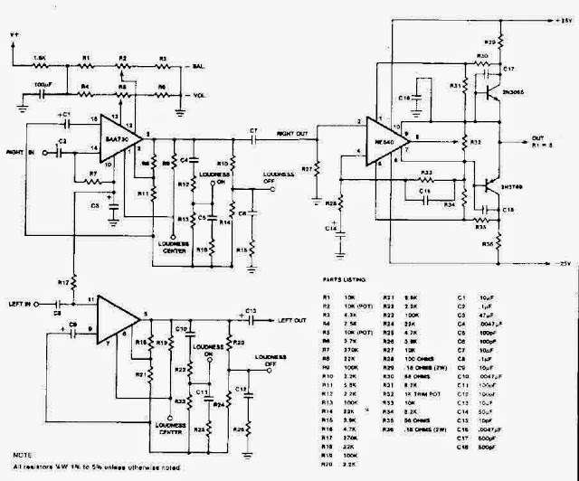
 Audio Preamplifier with balance loudness controls  Audio Preamplifier with balance loudness controls

Stereo Preamplifier With Bass Boost Circuit Diagram

Image
This is a simple project of Stereo Preamplifier With Bass Boost Circuit Diagram. High Quality, simple design, DC 20v to 30v supply This preamplifier was designed to cope with CD players, tuners, tape recorders etc., providing an ac voltage gain of 4, in order to drive less sensitive power amplifiers. As modern Hi-Fi home equipment is frequently fitted with small loudspeaker cabinets, the bass frequency range is rather sacrificed. This circuit features also a bass-boost, in order to overcome this problem. You can use a variable resistor to set the bass-boost from 0 to a maximum of +16dB @ 30Hz. If a fixed, maximum boost value is needed, the variable resistor can be omitted and substituted by a switch. Circuit Diagram:  Stereo Preamplifier With Bass Boost Circuit Diagram Parts: P1 = 10K P2 = 100K R1 = 100K R2 = 100K R3 = 15K R4 = 10K R5 = 22K R6 = 15K R7 = 1K R8 = 470R C1 = 2.2uF-25v C2 = 2.2uF-25v C3 = 470uF-35v C4 = 1uF-35V C5 = 2.2uF-25v C6 = 47nF-63v C7 = 22uF-25v IC1 = TL072, Op...

Phono Preamplifier Circuit Diagram

Image
Simple circuitry, Passive high-frequency equalization n recent years, following CD's introduction, vinyl recordings are almost disappeared. Nevertheless, a phono preamplifier is still useful for listening old vinyl discs from a well preserved collection. This simple but efficient circuit devised for cheap moving-magnet cartridges, can be used in connection with the audio power amplifiers shown in these web pages, featuring low noise, good RIAA frequency response curve, low distortion and good high frequency transients behavior due to passive equalization in the 1 to 20 KHz range. Circuit Diagram:  Phono Preamplifier Circuit Diagram Parts: R1 = 47K R2 = 100R R2 = 6.8K R4 = 68K R5 = 2.7K-1/2W R6 = 2.7K-1/2W R7 = 2.2K R8 = 39K C1 = 100uF-25V C2 = 100uF-25V C3 = 100uF-25V C4 = 47nF-63V C5 = 47nF-63V D1 = BZX79C18 D2 = BZX79C18 Q1 = BC337 Q2 = BC327 J1 = RCA Jack IC1 = LM833, Opamp Notes: R2, R3, R4, R7, R8, C4 & C5 should be low tolerance types. Schematic shows left channel and pow...