Posts

Showing posts with the label A

How to Make a Remote Control Circuit from a Remote Bell Unit

Image
The proposed remote control circuit idea can be used for controlling any electrical gadget within a range of 100 meters. Since the idea here is to modify an existing circuit of a remote bell unit, becomes super easy without any complications. However the construction part does require the involvement of electronic assemblies so this project may not be considered entirely a layman’s project. We all have seen and probably used remote bell gadget in our homes. The device is basically a wireless RF receiver and a transmitter set which can be used for producing alarm sounds remotely for calling or indication proposes. These gadgets are pretty effective with their functions and the specified operations are done efficiently across a considerable distance. The Chinese made remote bell units are best suited for the proposed project. Basically, when the transmitter of the remote bell is pressed, it sends a strong RF signal over a radial distance of approximately 100 meters. The...

Testing A FT245RL Chip with Software

Image
Chips FT245RL testing, checking for the program. It can set the output and input signals to the findings and submit. It is thus possible to enable or disable the 8 channels, for a 8-channel input. It all started a long time ago. Once, when I learned that the computer can be sent off signals that you can manage yourself, immediately began to take interest in the way they can do. It was somewhere in ~ 2002. After browsing the internet and found some examples of how the device can be connected to an LPT Port,. Since that time almost all computers have an LPT port, it's all gone well. In the LPT port connected LEDs managed a program written by someone that has been written as to support in the MS-DOS. It certainly was not a pleasant appearance, ease of operation ... Was only possible to manage such a procedure, a combination of ... as was intended by its creator. Therefore, once thought myself why can not I create and manage the program as he wants. So began an interest in computer pro...

A Simple MD Catridge Preamplifier

Image
Phonographs are gradually becoming a rarity. Most of them have had to yield to more advanced systems, such as CD players and recorders or (portable) MiniDisc player/recorders. This trend is recognized by manufacturers of audio installations, which means that the traditional phono input is missing on increasingly more systems. Hi-fi enthusiasts who want make digital versions of their existing collections of phonograph records on a CD or MD, discover that it is no longer possible to connect a phonograph to the system. Circuit diagram : A Simple MD Catridge Preamplifier Circuit Diagram However, with a limited amount of circuitry, it is possible to adapt the line input of a modern amplifier or recorder so that it can handle the low-level signals generated by the magnetodynamic cartridge of a phonograph. Of course, the circuit has to provide the well-known RIAA correction that must be used with these cartridges. The preamplifier shown here performs the job using only one opamp, four resisto...

How to wire up a Stomp Box Effects Pedal

Image
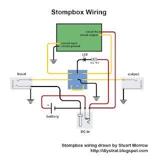
Today we're going to talk about how to wire up a stompbox. Apart from the effects circuit itself, there are three things that have to be thought about when wiring up a stompbox, which are the stomp switch, the stereo input jack and the DC-in connector. I’ll be referring to this image throughout the explanation (as with all images on here, click to enlarge): 1. The Switch To try to make this easy to follow, consider the left-hand column of the switch to be the input column, the middle column to be the LED column, and the right-hand column to be the output column. If for any reason you only have a 6-pin switch, you can still use it, just without the LED column. Off position In the OFF position, pin 4 is connected to pin 7, pin 5 is connected to pin 8, and pin 6 is connected to pin 9 (in my diagram at least – you may have a switch with different numbers written on it, though often they have none at all). Looking at just the left and right columns, the input comes in from the input jac...

13 8 Volt 20 A Transformerless Power Supply

Image
Do you need high current power supply without heavy and expensive transformer? Then, this circuit would be great choice for you. This 13.8 Volt 20 A regulated transformer less power supply. 20A transformer is very-very expensive, large in size and very heavy in weight. This power supply capable in delivers around 20Amps at 13.8V. For lower currents, a separate current limiting output, capable of 15ma up to a total of 20A has been added. Let us see what we have got here. The power transformer should be capable to deliver at least 25A at 17.5 to 20V. The lower the voltage, the lower power dissipation. The rectified current will be ironed by the C1, whose capacity should not be less than 40.000uF, (a golden rule of around 2000uF/A), but we recommend up to 50.000uF. This capacity can be built up by several smaller capacitors in parallel. The base of this design is a simple 12V regulator IC 7812.

Build a Mains Manager Circuit Diagram

Image
Mains Manager Circuit diagram. Very often we forget to switch off the peripherals like monitor, scanner, and printer while switching off our PC. The problem is that there are separate power switches to turn the peripherals off. Normally, the peripherals are connected to a single of those four-way trailing sockets that are plugged into a single wall socket. If that socket is accessible, all the devices could be switched off from there and none of the equipment used will require any modification.  Here is a mains manager circuit that allows you to turn all the equipment on or off by just operating the switch on any one of the devices; for example, when you switch off your PC, the monitor as well as other equipment will get powered down automatically. You may choose the main equipment to control other gadgets.  The main equipment is to be directly plugged into the master socket, while all other equipment are to be connected via the slave socket. The mains supply from the wall so...

DRIVING A BI COLOURED LED USING NE555

Image

FM Tracking Transmitter Using a 555 Timer

Image
Circuit diagram is designed for tracking transmitter audio tone in FM frequency band. Circuits that can be used the signal transmitter or remote control transmitter. In circuits that use only components that are available. Transmitter’s range is 100 m in the distance using the 9V power supply and matching the antenna. Circuit diagram is built by IC timer 555 to produce audio and tone based on the JFET in the circuit as the core. JFET circuit operation is the first (Q1) is the cable as a Hartley oscillator frequency modulated by the audio tone. The second (Q2) JFET is wired as a buffer to isolate the oscillator from the antenna based on the Q1. Diode D1 is used as varactor here. The diode is reverse bias voltage generated by slim on pin 2 & 6 of IC1 results. This change in capacitance of the junction diode reverse bias, which in turn change the frequency of the oscillator to achieve frequency modulation. For inductor L1 can be made by winding 5 turns of 18 SWG enameled copper wire o...

Hg Lamp to a Powerful UV Light Source

Image
I got myself some UV-curable solder mask for my PCB workshop, and as soon as i got it, i discovered that my UV artwork transfer box is totally incapable to activate the UV paint and cure it. I began searching the net for powerful UV lamps, and then it hit me: Some months ago i uploaded a theory regarding the Cold and Hot cathode discharge lamps. During my research for these lamps i found out that they can provide directly visible light (lamps without internal coating), or they produce UV radiation. The lamps that produce UV radiation have an extra coating on their internal surface which glows when excited by the UV rays, thus producing light! [ ]

Build a 60 dB Range Compressor For Audio

Image
A 60-dB Range Compressor circuit shown in the schematic diagram below can produce consistent output of 1.4V P-P over entire 60dB range that is very useful for audio level/volume stabilization.  As the main components, this circuit uses a 741 opamp and JFET. With input range of 20mV to 2oV, this circuit has delay time of 0.4s (decay time)  and response time of 1.2ms (attack time). The JFET is used as  voltage-controlled resistor in peak-detecting control loop of 741 opamp. Here is the schematic diagram of the circuit.  A 60-dB Range Compressor schematic diagram

Using an input device on Embedded Linux An example with a USB mouse on the Intel Edison

Image
The Intel Edison test board, along with the USB mouse I have recently been using the Intel Edison for the Cornell robotics project team (which co-hosts the Intel-Cornell Cup USA competition). Building on my previous knowledge of embedded systems, I started learning to use and program on Linux. The distro used is Yocto (all information is available on the Intel Edison website). One of the prototypes we worked on relied on using a wireless Playstation 4 controller for locomotion user interface. The concept of using an input device on Linux is not complicated, but can be a daunting task for someone new to Linux programming. Hence, I have decided to write this article giving an example of using an input device on an Embedded Linux platform. This demo application I am showing uses a USB mouse as the input device connected to the Intel Edison. Prerequisite: I have assumed that you have a flashed Intel Edison board, know how to access the terminal (through the USB COM port, or through SSH) a...

DRIVING A RELAY USING NE555

Image

Nikon D5500 Digital SLR format DX equipped with a swivel touch screen

Image
Nikon has announced the availability of portable digital SLR camera D5500, which the manufacturer has as its first camera format DX, equipped with a touch screen with variable angle. According to the manufacturer, its novelty is designed for lovers of creative photography who need more opportunities for self-expression. Due to the large matrix DX format and wide sensitivity range ISO (100-25 600 units) images are vivid and detailed. Due to the one-piece body design model D5500 is much thinner and lighter than its predecessor. A protruding handle makes it easy and comfortable to hold the camera. Highly sensitive touch screen with variable angle allows you to control the camera with the same ease as the smartphone, and built-in Wi-Fi makes it easy to transfer high-quality photos on a smart device. Main characteristics 24.2-megapixel DX-format without an optical low-pass filter 100-25 600 units of ISO 3.2-inch touch LCD monitor with variable angle, wide viewing angle and high resolution (...

Measuring Milliohms with a Multimeter Circuit Diagram

Image
Low values of resistance can be troublesome especially when large current s f low through them. A current of, say, 10 A passing through a terminal with a contact resistance of 50 m? will produce a voltage difference of 0.5 V. This resulting power loss of five watts is dissipated in the termination and can give rise to a dangerously high temperature which may degrade insulation around the wires.  . Measuring Milli ohms with a Multimeter Circuit Diagram Measuring Milliohms with a Multimeter Circuit Diagram . Measuring low values of resistance is not easy. Low cost multimeters do not include a milliohm measurement range and specialist equipment is expensive. The simple circuit described here allows milliohm measurements to be made safely on a standard ist equipment is expensive. The simple circuit described here allows milliohm measurements to be made safely on a standard multimeter. The circuit consists of little more than a 6 V voltage regulator and a mains adapter capable of suppl...

Making a Subwoofer Crossover Network

Image
The explained crossover network is designed for applications where an original audio system is required to be used with a sub woofer speaker system. This could be any sub woofer idling in your store room. If the frequency specs of the loudspeaker are rated far down the spectrum then its better, nevertheless filter becomes always a handy option for the same in much effective way. Usually a sub woofer circuit is in the form of an active filter, but with the botheration of having a separate power supply for powering the circuit. The proposed sub woofer crossover network is a passive type by nature which allows the audio signal itself to get filtered through the associated passive components arranged in a calculated configuration. Owing to the fact that the low frequency bass signal may be equally present in both the channels of the stereo signals, any of the channels may be used as the input source for feeding the sub woofer filter through an appropriate amplifier stage. ...

A Doorbell for the Deaf Circuit Diagram

Image
This circuit provides a delayed visual indication when a door bell switch is pressed. In addition, a DPDT switch can be moved from within the house which will light a lamp in the door bell switch. The lamp can illuminate the words "Please Wait" for anyone with walking difficulties. A Doorbell for the Deaf Circuit Diagram : Notes : The circuit uses standard 2 wire doorbell cable or loudspeaker wire. In parallel with the doorbell switch, S1, is a 1N4001 diode and a 12 volt 60mA bulb. The bulb is optional, it may be useful for anyone who is slow to answer the door, all you need to do is flick a switch inside the house, and the bulb will illuminate a label saying Please Wait inside the doorbell switch or close to it. The double pole double throw switch sends the doorbell supply to the lamp, the 22 ohm resistor is there to reduce current flow, should the doorbell switch, S1 be pressed while the lamp is on. The resistor needs to be rated 10 watts, the 0.5 Amp fuse protects against...

Build a Passive Infrared Sensor Circuit

Image
What is PIR ?Passive Infrared Sensor Circuit Diagram. Detectors or pyroelectric sensors, passive infrared or PIR sensor, are made of a crystalline material that generates an electric charge on the surface when exposed to heat in the form of infrared radiation. When radiation increases the amount of electrical charge increases too and this load is measured with a sensitive FET transistor which is inside the sensor module. With the RIP is commonly used as a motion detector of an object by detecting the infrared signal radiated from the object (people and animals). The Passive Infrared Sensors are also used in remote thermometers. Pin 1 of the PIR must be connected to the positive supply 5V DC. Pin 2 is the output of PIR sensor, it must have a connection to the earth through a resistor of 47K to 100K (depending on the circuit). Pin 3 of the RIP must be connected to ground or negative circuit.   Simple Circuit Diagram using PIR Sensor Simple circuit motion sensor PIR detector. Conne...

Using a single 7812 IC 12 Volt 30 Amp Circuit Diagram

Image
This is the Using a single 7812 IC - 12 Volt 30 Amp Circuit Diagram simple project. Using a single 7812 IC voltage regulator and multiple outboard pass transistors, this power supply can deliver output load currents of up to 30 amps. Notes: The input transformer is likely to be the most expensive part of the entire project. As an alternative, a couple of 12 Volt car batteries could be used. The input voltage to the regulator must be at least several volts higher than the output voltage (12V) so that the regulator can maintain its output. If a transformer is used, then the rectifier diodes must be capable of passing a very high peak forward current, typically 100amps or more. The 7812 IC will only pass 1 amp or less of the output current, the remainder being supplied by the outboard pass transistors.  As the circuit is designed to handle loads of up to 30 amps, then six TIP2955 are wired in parallel to meet this demand. The dissipation in each power transistor is one sixth of the to...

Auto LED Taillight for a Bike

Image
This is a circuit for automatically switching off and LED taillight for a bike. The backlight turns on by movement (in the dark). After about 20 minutes of inactivity, the backlight is switched off again. So you cannot forget to turn off the backlight so that you are less likely surprised by batteries.  Auto LED Taillight Circuit Diagram S1 is a motion switch. When the switch closes C1 is charged. Therefore FET switches T1 and burn the LED. T1 can however only enabled when R3 is sufficiently high resistance, or when it is dark. R1 C1 discharge slowly so that after about 20 minutes the FET turns off and the LED goes out. The circuit may be built into the housing of a rear light on the battery that is inexpensive to buy in the market. That way you already have a beautiful body. Parts List:      R1 = 2.2 MΩ      R2 = 2,2 kohm      R3 = LDR      R4 = 220 K?      R5 = 22 K?   ...

Build a Faulty Car Indicator Alarm Circuit Diagram

Image
Build a Faulty Car Indicator Alarm Circuit Diagram, Before taking a turn, either left or right, car drivers need to switch on the car’s turn- indicator lamps so that the approaching vehicle drivers can take precaution accordingly. An accident is likely to occur in case your car’s turn- indicator lamps fail to glow due to some reason or the other. Here’s a circuit that sounds an alarm if your turn- indicator lamps don’t glow, helping you to safeguard against any accident. When both the the front and rear turn- indicator lamps (either right or left) glow, the current through the lamps (L1-L2 or L3-L4) causes a voltage drop across series resistor R1. This voltage drives pnp transistor T1 into saturation. In this condition, pnp transistor T2 does not conduct and hence relay RL1 does not energise. No sound from piezobuzzer PZ1 (connected to normally-opened (N/O) contacts of relay RL1) means that the turn- indicator lamps are working satisfactorily. Faulty Car Indicator Alarm Circuit Di...