Posts

Showing posts with the label Radio

FM Radio Transmitter schematic with pcb
Image
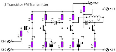
For those of you like / love to talk in the air can assemble this simple circuit that can be received by the radio receiver to within a few hundred feet. The voice that issues by this circuit at all clear without rustling. Can also be used to link communications over the air using this radio transmitter, provided that other person also had the same circuit. This PCB design : Description : Resistor R1__________________1K R2__________________18K R3__________________82K R4__________________1K2 R5__________________5K6 R6__________________39K R7__________________18K R8__________________68K R9__________________470R R10_________________100R R11_________________50K XTal Q1__________________ Crystal according to the desired frequency Inductor L1__________________10uH Capacitor C1__________________10uF C2__________________30uF C3__________________20uF C4__________________47uF Transistor Tr1_________________2SB175 Tr2_________________2SB175 Tr3_________________2SB178 Antenna X1-1________________...

Easy to Use FM Radio Receiver

Image
The project is a user-friendly and cheap FM radio receiver which produces the desired audio signals using integrated circuit to achieve the pre-processing units. During operation, the user is allowed to change stations and interact with the receiver by integrating a keypad and an LCD for communication. There are several functions that this radio receiver can perform including adjusting the threshold when picking up stronger or weaker stations, setting up 3 favorite stations for quick tuning, scanning up/down for next strong signal station, and tuning up/down a frequency. A keypad is designed for controlling the receiver and the buttons are mapped to their corresponding functionality while the other buttons are not connected. The 4 main sub-components of the receiver include the LCD, the keypad, the favorite station storage, and the communication with receiver. Each of them is being controlled by their software components. The antenna transfers the incoming radio signal to the AR1010 F...

FM Radio Receiver Circuit Diagram

Image
This simple circuit FM radio receiver comprises a step of regenerating rf, TR1, followed by a two-stage three audio amplifiers, TR2 to TR4. A critical part of the FM radio receiver is the first stage, TR1/VC1 where the wiring should be kept as short as possible. Coil L1 consists of 8 turns of the winding 1 mm (20 AWG) enamelled copper wire 6 mm in diameter L1 should then be thoroughly and uniformly stretched to a length of about 13mm.  FM Radio Receiver Circuit Diagram The tuning capacitor VC1 is one of two sections of a fm radio FM miniature, it is connected to the capacitor C1 22pF. The inductance value L2 rf is not critical, since anything 1μH to 10μH. The output is suitable for common headphones connected in series to provide an impedance of 64Ω. List of Transistors TR1 = BF199 TR2 TR3 TR4 == = BC547

Portable Satellite Radio and MP3 Player XM XPMP3H1

Image
The XMp3i Portable Satellite means of communication combines satellite radio and MP3 capabilities into a single compact package. This efficient device shows comedian celebrity, song title, and channel in rank on a hefty color exhibit. The device lets you browse and explore other songs and artists lacking leaving your current channel. join up the XMp3i with an XM subscription design to facilitate preeminent suits you and start enjoying all your favorite harmony, gossip, and entertainment on the contact of a button. Individual SiriusXM brings you added of pardon? you be keen on, all happening lone place. take pleasure in industrial-limitless harmony from practically each genre - together with musician-devoted channels. induce live sports act-by-play and 24/7 expert natter. have the benefit of exclusive entertainment and comedy. Plus the human race-lecture news, community traffic and weather, and added. elect amid the first-class, primary before All Access training package.