Posts

High Power Audio Amplifier 2800W Circuit Schematic Diagram

Image
Description Mono high power amplifier is actually a powerful 1400 W, but if this hihgh power amplifier circuit is doubled and you want to create stereo, high power amplifier the necessary components and pcb requires two-fold. So if the stereo high power amplifier 2 X 1400W. Schematic Circuit diagram is still less by looking at the circuit that was so below, the finished circuit has been added with a gains using JRC4558 IC by the two and the picture ic where it can be seen below. For circuit buffers, drivers , and booster use multiple transistors and other components (can be seen listed component ). And high power amplifier project that is so below is just part of the buffer and driver while the booster has not been made​​. For additional transistors in the booster or high power amplifier end scheme can be found Booster output power amplifier. Circuit Schematic Diagram : Part List : R1_____560Ω R2_____100Ω R3_____2K2Ω R4_____560Ω R5_____1Ω R6_____27KΩ R7_____10KΩ R8_____100Ω R9___

125MHz Dev Board with an ARM Cortex M3

Image
The Simplecortex is a microcontroller development board that is shield compatible with the Arduino. The Simplecortex has a fast microcontroller, the LPC1769 from NXP. This is a ARM Cortex M3 microcontroller with 512KB flash, 64KB RAM and it runs at 120Mhz. To make sure that the Simplecortex is easy to use we made tutorials for almost every peripheral on the chip and examples to get you started. There are tutorials for simple stuff like IO control up to more advanced tutorials for MicroSD cards. If you have ideas for a new tutorial or made a tutorial yourself, feel free to drop an email or post it in the forum. The Simplecortex also has an onboard debugger. It can also be used to program external devices like a self made PCB for your own project. No more microcontrollers with pre-programmed bootloader needed.        [ ]

Crowbar Speaker Protection Circuit Diagram

Image
This is the Crowbar Speaker Protection Circuit Diagram. Crowbar circuits are so-called because their operation is the equivalent of dropping a crowbar (large steel digging implement) across the terminals. It is only ever used as a last resort, and can only be used where the attached circuit is properly fused or incorporates other protective measures. A crowbar circuit is potentially destructive - if the circuitry only has a minor fault, it will be a major fault by the time a crowbar has done its job. It is not uncommon for the crowbar circuit to be destroyed as well - the purpose is to protect the device(s) attached to the circuit - in this case, a loudspeaker. Description There's really nothing to it. A resistor / capacitor circuit isolates the trigger circuit from normal AC signals. Should there be enough DC to activate the DIAC trigger, the cap is discharged into the gate of the TRIAC, which instantly turns on ... hard. A TRIAC has two basic states, on and off. The in-between s

Blown Fuse Monitor Circuit

Image
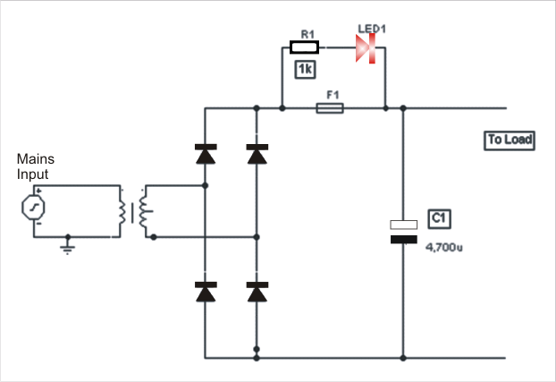
The post explains a simple fuse monitor or indicator circuit, for indicating the fuse status anytime. This is one of the simplest yet effective alarm cum monitor for detecting any blown fuse. A resistance of value 1K is placed in series with a LED and connected across the fuse which is to be tested. Normally when the fuse is healthy, LED 1 will not get any bias. Thus, it will not raise an alarm. However, the moment the fuse is blown , LED1 gets a feed in bias and starts to glow. The value of the resistor R1 and its wattage should obviously be decided depending on the type of LED and the supply across it. Suitably connecting a 12V zener and a 12V electronic buzzer across the fuse can enable an audio output (alarm sound) if so required.

Speech Filter

Image
In communications receivers and microphone amplifiers for transmitting equipment, there is frequently a need for a narrow, low-frequency band-pass filter that lets only the voice band through. This band is usually defined to be the portion of the audio frequency spectrum between approximately 300 Hz and 3300 Hz. In order to implement such a filter, we have calculated the values for two fifth-order Butterworth filters having these corner frequencies and connected them in series. The result is a band-pass filter for the desired pass-band with a skirt steepness of 100 dB/decade.  The first opamp (IC1) acts as a buffer. Speech Filter Image :   The circuit can be powered by a unipolar supply voltage between 5 V and 18 V, which is a broad enough range that it should always be possible to find a suitable voltage when building the filter into existing equipment. The current consumption of the filter is only a few milliampères, which should rarely pose a problem. There is fairly wide selectio

Timer with Musical Alarm Circuit Diagram

Image
The timer with Musical Alarm  use famous CMOS oscillator/divider IC (IC1 ). Although this circuit operates in 9V its standby current drain is very low. The time delay of timer circuit can be adjusted by adjusting the preset VR1. The base of npn transistor T1 is connected to pin 3 of IC1 through resistor R4 and its emitter terminal is connected with pin 2 of melody generator IC­ (IC2) in order to provide positive supply when adjusted time delay is over. Timer with Musical Alarm Circuit Diagram Here the zener diode ZD1 is used as regulator which reduce power supply to required for operation of IC2 i.e. 3.3V. Lastly for music output the output from pin 1 of IC2 is fed to loud speaker via driver transistor and its volume is controlled by preset VR2. For starting the timer power is supplied by pressing switch SW1. Parts list Resistor (all ¼-watt, ±5%) R1 = 1.2 MΩ R2 = 2.2 MΩ R3 = 56 KΩ R4, R5, R6 = 1 KΩ VR1 = 1 MΩ VR2 = 1 KΩ Capacitors C1 = 0.01 µF C2 = 0.22 µF C3 = 1 µF/25V Semiconductor

10 Minutes Timer Using 555 Timer IC

Image
Applications of 555 timer IC is very diverse, one series of 10 Minute Timer with IC 555. 10 Minute Timer This circuit uses IC NE555 is set as a monostable multivibrator.  The timing of the timer circuit 10 minutes with the IC 555 is governed by the configuration of C2, R4 and R5. The greater the value of C2 at 10-minute timer circuit with IC 555 timer is active then the time will stay longer. Total resistance value between R4 and R5 also determine the active circuit 10 minute timer with IC 555, where the greater the value the longer time was also active. 10 Minutes Timer Using 555 Timer IC Circuit  Schematic The core active setting the timer on the set of C2 charging time for 10 minutes on the timer circuit with IC 555. So, with the value of C2 remain so with time on the circuit timing Timer 10 minutes by IC 555 can be set by changing the resistance value R 4 + R 5. Indicators of active timer at 10 minute timer circuit with IC 555 uses the LED D2 and D3 will light up only one course to