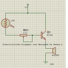
Simple Sensitive Optical Burglar Alarm Circuit Diagram
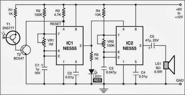
How to build a Simple Sensitive Optical Burglar Alarm Circuit Diagram ? This optical burglar alarm uses two 555 timer ICs. Both the ICs are wired as astable multivibrators. The first astable multivibrator built around IC1 produces low frequencies, while the second astable multivibrator built around IC2 produces audio frequencies. Simple Sensitive Optical Burglar Alarm Circuit Diagram General-purpose Darlington photo-transistor 2N5777 (T1) is used as the light sensor. To increase the sensitivity of the circuit, npn transistor BC547 (T2) is used. Place phototransistor T1 where light falls on it continuously. Phototransistor T1 receives light to provide base voltage to transistor T2 . As a result, transistor T2 conducts to keep reset pin 4 of IC1 at low level. This disables the first multivibrator (IC1) and hence the second multivibrator (IC2) also remains reset so the alarm (loudspeaker LS1) does not sound. When light falling on Darlington phototransistor T1 is obstructed, transistor