Posts

Showing posts from November, 2016

FM Radio Receiver Circuit Diagram

Image
This simple circuit FM radio receiver comprises a step of regenerating rf, TR1, followed by a two-stage three audio amplifiers, TR2 to TR4. A critical part of the FM radio receiver is the first stage, TR1/VC1 where the wiring should be kept as short as possible. Coil L1 consists of 8 turns of the winding 1 mm (20 AWG) enamelled copper wire 6 mm in diameter L1 should then be thoroughly and uniformly stretched to a length of about 13mm.  FM Radio Receiver Circuit Diagram The tuning capacitor VC1 is one of two sections of a fm radio FM miniature, it is connected to the capacitor C1 22pF. The inductance value L2 rf is not critical, since anything 1μH to 10μH. The output is suitable for common headphones connected in series to provide an impedance of 64Ω. List of Transistors TR1 = BF199 TR2 TR3 TR4 == = BC547

TDA2003 made for Car amplifier circuit

Image
This is a very popular series of amplifiers audio users who require maximum aduio results and of course with a relatively cheap price. This circuit requires a minimum voltage and maximum 9 Volt and 30 Volt. This amplifier circuit using ic TDA2003, which is used in car audio power, because of making these amplifiers can easily be made on each speaker of the amplifier. By using ic and component quality is very good circuit used separately. The circuit can be seen below.   Technical information: Supply voltage = 12V Output             = 10W 

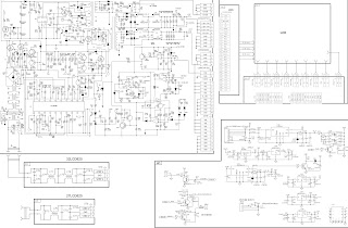
Horizont 27LCD825 – Horizont 32LCD825 – LCD TV – Circuit diagram Schematic

Image
SMPS MAIN BOARD Click on the schematics to zoom in

Router UPS

Image
It can be handy to have your phone and Internet router continue working for a while after  a power failure for example, if they provide  access to a security system. This requires a  backup power supply for the router. The version described here consists of a 12-V lead-acid battery and a voltage converter capable  of supplying an output voltage in the range of  15 to 30 V. It has built-in protection to prevent  excessive battery discharge.  This DIY uninterruptible power supply (UPS)  operates in standby mode as long as the  mains voltage is present.  Circuit diagram : Router UPS Circuit Diagram The UPS consists of four parts: a backup  detector circuit that monitors the supply  voltage from the AC mains adapter, a battery  circuit that monitors the battery voltage to  prevent it from dropping below 11.8 V, a FET  switch between the battery and the voltage  converter, and a voltage doubler (inside the  dashed outline). To understand how it works, first consider  the situation with a r

Infra Red Switch

Image
Description:  This is a single channel (on / off) universal switch that may be used with any Infra Red remote control that uses wavelengths between 850-950nm. Circuit diagram  Notes:   Any "button" of any remote control may be used to work this universal switch. The button must be pressed for two seconds (determined by R3 and C2) before the relay will operate. Once operated the circuit will remain in this state (latched) until reset. To reset, any button is pressed and held for the delay. For example, if you were watching TV, and your set was tuned to Channel 3, you could press and hold the TV remote controls channel 3 button for two seconds. That way the TV viewing would not be affected and the relay would activate. You can connect anything to the relay, for example a lamp, but make sure that the relay contacts can handle the rated voltage and current.  Circuit Operation:   IC1 is an Infra Red module. IR modulated pulses are received and buffered by this IC. It has a standar

Simple Mini FM Receiver

Image
This is the most simple fm radio receiver with good performances that works great even if the sensitivity is not too high. The working principle of this fm receiver may seem a little unusual. It is made of an oscillator (T2 and T3) that is synchronized with the received frequency of T1. This transistor works as a broadband preamplifier in VHF range. Mini FM Receiver Circuit Diagram : The oscillator is adjusted between 87 … 108 MHz with C5. Because of the synchronization, the oscillator output will have the same frequency deviation as the received signal from the fm antenna. This deviations are caused by the broadcasted audio informations. The frequency modulated signal show up on P1 + R5. Low pass filter R6/C6 extracts the audio signal and then is amplifier by T4 … T6 and transmitted at the output through C9 capacitor. The coil details are presented in the fm receiver circuit diagram. The radio receiver is adjusted on different stations with the help of C5. P1 potentiometer is adjusted

Audio Preamplifier with balance loudness controls

Image
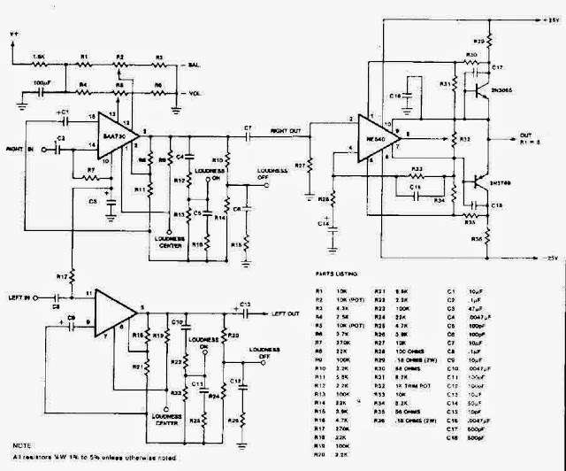
 Audio Preamplifier with balance loudness controls  Audio Preamplifier with balance loudness controls

6 Watt 4 Ohm Amplifier Circuit

Image
This is an audio amplifier circuit based on IC, and IC were used that MPC563 with minimal output 6W, with impedance of 4 Ohm. Supply Voltage Minimum 4 Volt DC and a maximum voltage to 20 Volts DC. See him under this Scheme. 6 Watt 4 Ohm Amplifier Circuit

Car Reversing Horn With Flasher

Image
Here is a simple circuit that starts playing the car horn whenever your car is in reverse gear. The circuit (refer Fig. 1) employs dual timer NE556 to generate the sound. One of the timers is wired as an astable multivibrator to generate the tone and the other is wired as a monostable multivibrator. Circuit diagram : Fig. 1: Car Reverse Horn Circuit Diagram Working of the circuit is simple. When the car is in reverse gear, reverse-gear switch S1 of the car gets shorted and the monostable timer triggers to give a high output. As a result, the junction of diodes D1 and D2 goes high for a few seconds depending on the time period developed through resistor R4 and capacitor C4. At this point, the astable multivibrator is enabled to start oscillating. The output of the astable multivibrator is fed to the speaker through capacitor C6. The speaker, in turn, produces sound until the output of the monostable is high. When the junction of diodes D1 and D2 is low, the astable multivibrator i

BASKETBALL COURT DIAGRAM

Image
Simple basketball court Full basketball court on one ... Printable Basketball Court ... Half-Court - U.S. Version Basketball court vector ... ... Diagram Of Soccer Field ... US half-court diagram basketball%20court%20clipart% ... Green Diagram, Half court ... basketball court diagram

Signal Tracer Circuit Diagram

Image
This is the simple Signal Tracer Circuit Diagram. The main part of this circuit is the LM386 amplifier chip. It also uses a transistor input to buffer the input signal and provide extra gain for the LM386. The little unit has helped me out on numerous occasions when trouble shooting any amplifier circuit like a stereo receiver, tv / vcr audio section, radios, cd players and car stereos. Signal Tracer Circuit Diagram

Tracking Battery Charger IC Supports Solar Power Systems

Image
Individual solar-panel systems produce dc power for remote applications while also storing energy in a rechargeable battery supported by a battery-charger IC. In non-utility grid applications solar panels produce dc power for emergency roadside telephones, navigation buoys, and other remote loads. Virtually all 12-V-system solar panels comprise a series of photovoltaic cells that have a maximum output power of less than 25 W. In producing this power the solar-panel system uses a battery to provide power when the panel is “dark.” The rechargeable battery can supply power for long periods of time, requiring a charger that can properly operate a solar panel. Meeting this need is Linear Technology’s LT3652 monolithic buck-charger IC, which operates with a single solar panel. The IC uses average-current-mode control-loop architecture to provide constant current/constant voltage (CC/CV) charge characteristics with a programmable charge current. The charger can be programmed to produce a 14.4

Bully FM radio signals

Image
Interfere with fm radio signal is fun, if you're bored or no work, you can do at home, where neighbors , at school , or even near the transmitter. With the circuit above you can interfere with the speech signal in condenser microphone , and the signal will be issued by the circuit will then be received by FM radio receiver and a voice that we remove it before going out mixed with the signals emitted by radio FM transmitter. Part List : R1  = 4K7 R2  = 2K2 C1  = 1n5 C2  = 47pF C3  = 33pF L1  = Nikelin wire coil with a diameter 0,8 mm and 5mm in diameter wound coil 10 x T1  = 2N3906 Mic= Condenser Microphone If the circuit does not work on the errors may occur : Installation of the opposite transistor , incorrect placement of components , less voltage, the voltage is too high , the microphone is broken, transistor is damaged , broken coil . Please note this circuit can work and receive FM radio reciver at distance of about 500 meters. And not to much use , because the radio will be a

Drop Voltage Indicator

Image
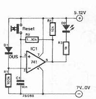
An indicator of drop voltage can be achieved using electronic diagram below. This indicator shows the drop voltage or disturbing impulses of any existing network using a LED which will light. Drop Voltage Indicator Circuit Diagram This circuit can be powered with a DC voltage between 5 and 12 volts.

Apples highly anticipated iPhone5S

Image
  Apple’s iPhone5S and its cheaper version in plastic 5C are expected to be unveiled on September 10 but it might not see great levels of excitement and big crowds. MSN Money said that the reason was a cold response can be attributed to the fact that the new iPhone is no longer a ‘cultural phenomenon’ as rivals like Samsung are making smartphones that are just as good, News.com.au reports. iPhone 5S is expected to be of the same size as iPhone 5, which means it will still be smaller than the Samsung Galaxy S3 and S4. MSN said that the new device may have a fingerprint reader and have ‘tweaks’ rather than real advancements and the biggest thing it will lack is major innovation, something for which the software giant was well known for during the Steve Jobs days, the report added.[via]

Speaker Microphone Circuit

Image
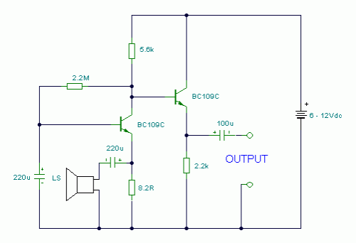
Description: This circuit takes an ordinary loudspeaker and allows it to be used in reverse, as a microphone. Circuit diagram Notes: This circuits allows you to use a cheap loudspeaker as a microphone.Sound waves reaching the speaker cone cause fluctuations in the voice coil. The voice coil moving in the speakers magnetic field will produce a small electrical signal . The circuit is designed to be used with an operating voltage between 6 and 12 volts dc. The first transistor operates in common base mode. This has the advantage of matching the low input impedance of the speaker to the common base stage, and secondly has a high voltage gain. The second stage is direct coupled and operates in emitter follower. Voltage gain is slightly less than unity, but output impedance is low, and will drive long cables. Speech quality is not as good compared to an ordinary or ECM microphone, but quite acceptable results can be obtained. Speaker cones with diameters of 1 inch to 3 inches may be used. S

Toy Siren Circuit Diagram

Image
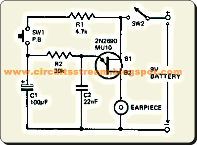
This simple Toy Siren circuit for hobbyist and student who game liker, this is a very simple Toy Siren circuit,  This Toy Siren circuit can be built small enough to frt inside a toy. The Toy Siren circuit consists of a relaxation oscillator utilizing one uni-junction transistor (2N2646, MU10, TIS43). R2 and C2 determine the frequency of the tone.   Simple Toy Siren Circuit Diagram Pushing the button, SW1 charges up the capacitor and the potential at the junction of R2 and C2 rises, causing an upswing in the frequency of oscillation. On releasing the push-button the charge on C2 will drop slowly with a proportional reduction in the frequency of oscillation. Manual operation of the button at intervals of approximately 2 seconds will produce a siren sound. Sourced By: Circuitsstream

Infrared Proximity Detector Alarm

Image
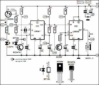
The below circuit can be built from readily available low-cost components, some of which may even be hiding in your junk box! The indicated value of 22 Ω for resistor R1 causes an average current of about 65 mA through infrared emitter D1. Because the IRED is pulsed at a duty factor of about 50% through the action of T1 and IC1, a peak current of 128 mA flows during every half cycle. This may seem a lot but in fact is well within the safe specification of the LD274. The LM567 PLL IC is configured to supply a switching frequency of about 20 kHz. When the infrared beam emitted by D1 is reflected by a nearby object, IC1, through receiver diode D2 and transistor T2, receives the recovered 20 kHz signal at its input, pin 3.  Circuit Diagram Because the ‘567 PLL is then locked, the IC output (pin 8), drops low, triggering the 555 chip in monostable mode (IC2) and so causing acoustic actuator Bz1 to sound. The monostable remains on as long as the reflected signal is being received. Because of t

Video Isolator Circuit Diagram

Image
These days many more audio-visual devices in the home are connected together. This is especially the case with the TV, which may be connected to a DVD player, a hard disk recorder, a surround-sound receiver and often a PC as well. This often creates a problem when earth loops are created in the shielding of the video cables, which may cause hum and other interference. The surround-sound receiver contains a tuner that takes its signal from a central aerial distribution system. The TV is also connected to this and it’s highly likely that the PC has a TV-card, which again is connected to the same system. On top of this, there are many analogue connections between these devices, such as audio cables. The usual result of this is that there will be a hum in the audio installation, but in some cases you may also see interference on the TV screen. The ground loop problem can be overcome by galvanically isolating the video connections, for example at the aerial inputs of the surround-sound rece

Simple 12 Vdc 120 Vac Inverter Circuit Diagram

Image
This is the Simple 12 Vdc - 120 Vac Inverter Circuit Diagram. An Inverter is a device that converts 12 volts d.c to 120 volts a.c. , which is what we use in our homes.  This project will handle about 300 watts, which is perfect for lights, small T.V.'s and radio equipment. This Inverter takes 12 volt d.c  and steps it up to 120 volt a.c.  The wattage depends on which transistors you use for Q1 and Q2, as well as the "Amp Rating" of the transformer you use for T1. This inverter can be constructed to supply anywhere from 1 to 1000 (1 KW) watts. If Q1, Q2 are 2N3055 NPN Transistors and T1 is a 15 A transformer, then the inverter will supply about 300 watts. Larger transformers and more powerful transistors can be substituted for T1, Q1 and Q2 for more power.  Simple 12 Vdc - 120 Vac Inverter Circuit Diagram Note: Don't try to run inductive loads (motors...) off this inverter. Parts    C1, C2        68 uf, 25 V Tantalum Capacitor R1, R2        10 Ohm, 5 Watt Resistor R3,

Simple NiCd Battery Charger

Image
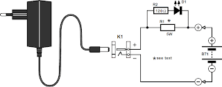
The design of the charger is similar to that of many commercially available chargers. The charger consists of a mains adaptor, two resistors and a light-emitting diode (LED). In practical use, this kind of charger is perfectly all right. Resistor R1 serves two functions: it establishes the correct charging current and it drops sufficient voltage to light the diode. This means that the LED lights only when a charging current flows into the battery. The charging current is about 1/4 of the battery capacity, which allows a slight overcharging, and yet the charging cycle is not too long (4–5 hours). Simple NiCd Battery Charger  Circuit diagram:   The value of the resistors may be calculated as follows, for which the nominal e.m.f. and the capacity of the battery must be known. Adjust the output of the mains adaptor to 1.17 times the nominal battery voltage plus 3.3 V, which is the potential across R1. Note that the adaptor must be capable of supplying a current of not less than half the ba

Invisible Broken Wire Detector Circuit Diagram

Image
This is a project of Invisible Broken Wire Detector Circuit diagram. Portable loads such as video cameras, halogen flood lights, electrical irons, hand drillers, grinders, and cutters are powered by connecting long 2- or 3-core cables to the mains plug. Due to prolonged usage, the power cord wires are subjected to mechanical strain and stress, which can lead to internal snapping of wires at any point. In such a case most people go for replacing the co e/cable, as finding the exact loca Portable loads such as video cameras, halogen flood lights, electrical irons, hand drillers, grinders, and cutters are powered by connecting long 2- or 3-core cables to the mains plug. Due to prolonged usage, the power cord wires are subjected to mechanical strain and stress, which can lead to internal snapping of wires at any point.  In such a case most people go for replacing the core/cable, as finding the exact location of a broken wire is difficult. In 3-core cables, it appears almost impossible to d

Fuse Monitor Indicator

Image
This electronic circuit project of fuse monitor indicator, its a very simple way to check if a fuse has blown without removing it from its holder. Fuse Monitor Indicator Circuit Diagram: The idea for this project may have come to me in a flash of inspiration

Telephone transmitter

Image
Description. This is a simple, but very useful circuit that can be used to transmit telephone conversations. When the telephone receiver is on hook the voltage across the lines will be about 48 volts. The preset R7 is so adjusted to obtain a 24.7 V across between the cathode of D2 and ground. At this voltage the Zener diode D2 will be in breakdown and the transistor T1 will conduct. This makes the transistor T2 OFF. When the receiver is off hook, the line voltage drops to about 11 volts. This makes the transistor T1 OFF and subsequently the T2 ON. The T2 in switched ON condition will provide a DC path for the transistor T3 used in the FM transmitter section. The transistor T3 is wired as a common emitter radio frequency oscillator. In simple words the transistor T2 serves as an ON/OFF switch for this oscillator. The modulated signal will be available at the collector of transistor T3 and the signal id fed to the antenna via capacitor C5. Circuit diagram with Parts list. Notes. Asse

Simple 500 Watt Inverter Circuit Diagram

Image
This is a Simple 500 Watt Inverter Circuit Diagram . Power inverter is a very useful device which can convert Low voltage from a DC source to high voltage AC. The most common power inverter is 12V to 240V inverter. Perhaps that is because 12V batteries are common. This type of power inverter usually draws current from a DC battery. This battery should be able to provide a high flow of electric current. Normally lead acid batteries can server this purpose well. This current is then converted to 240V square wave alternative current so that we may empower those electric appliances which work on 240V instead of 12V. Inverter falls in the category of expensive devices so many people don’t buy them even they need them. What if I tell you how to build an inverter yourself? Simple 500 Watt Inverter Circuit Diagram I remember when I build my first inverter, I was very happy and I invited a lot of friends to see my homemade inverter. I am sure you will feel the same. Before you start building th

AMN12111 PIR Motion Sensor

Image
PIR movement sensor module (Passive Infra Red) motion detection sensor AMN12111 is the smallest of objects the size of its shape. PIR motion sensor module (Passive Infra Red) AMN12111 fresneal come equipped with a lens. PIR motion sensor module (Passive Infra Red) AMN12111 has advantages can be directly connected to the microcontroller or other actuator driver. PIR movement sensor module (Passive Infra Red) AMN12111 has a sensitivity that is very sensitive to changes in motion around it. PIR movement sensor module (Passive Infra Red) AMN12111 very suitable when applied to security systems. The price of the PIR movement sensor module (Passive Infra Red) AMN12111 not quite expensive. readily available in the market. For those of you who want to make a motion detection sensor. PIR movement sensor module (Passive Infra Red) AMN12111 is much easier and more practical than you have to make a series of Infra Red with the Tx and Rx.

Simple Distance Counter Circuit Diagram

Image
Presented here is a simple pedometer circuit. It measures the distance covered by you while walking. It may not work very well for running! Circuit and working Fig. 1 shows circuit diagram of the distance counter. The circuit is built around quad 2-input Schmitt trigger CD4093 (IC1), CMOS ripple carry binary counter/divider CD4024 (IC2), decade counter/divider CD4026 (IC3 and IC4), two transistors BC327 (T1, T2) and some other components.   Fig. 1: Circuit diagram of the distance counter Fig. 3: An actual-size, single-side PCB for the distance counter Fig. 4: Component layout for the PCB Gates N1 and N2 of IC1 form a monostable multivibrator that receives trigger input from tilt or mercury switch S1. When you lift your foot up and touch the ground back during walking, the mercury inside the switch makes a contact with its two metallic leads as shown in Fig. 2. This makes the current to flow between the metallic leads and a pulse is generated at pin 4 of IC1.    Fig. 2: Open-close oper

simple Acoustic Sensor Circuit Diagram

Image
This acoustic sensor was originally developed for an industrial application (monitoring a siren), but will also find many domestic applications. Note that the sensor is designed with safety of operation as the top priority: this means that if it fails then in the worst-case scenario it will not itself generate a false indication that a sound is detected. Also, the sensor connections are protected against polarity reversal and short-circuits. The supply voltage of 24 V is suitable for industrial use, and the output of the sensor swings over the supply voltage range.   Circuit diagram : The circuit consists of an electret micro-phone, an amplifier, attenuator, rectifier and a switching stage. MIC1 is supplied with a current of 1 mA by R9. T1 amplifies the signal, decoupled from the supply by C1, to about 1 Vpp. R7 sets the collector current of T1 to a maximum of 0.5 mA. The operating point is set by feedback resistor R8. The sensitivity of the circuit can be adjusted using potentiometer

Dog Whistle for Ronja

Image
Ronja is the author’s dog, a beagle-mongrel,  who seems increasingly often to need to be  called to heel either with a shout or with a  whistle. And so the idea came about for an  electronic dog whistle that could produce  two alternating high-frequency tones. A  design like this has several advantages over  conventional whistles or calling.   Circuit diagram : Dog Whistle for Ronja Circuit Diagram   You can continue to carry on a conversation with your friends without having to  stop to whistle or call to your dog. Using high frequencies means that  the whistle sound is barely audible to  (especially older) humans and so is less  annoying to other people than conventional whistles or calls. As is well known,  dogs have rather better hearing than  we do and can hear frequencies of up to  40 kHz. The two alternating pitches mean that the  dog can more easily distinguish it from  other whistles.   The dog whistle is constructed from two  standard 555 timer ICs (or a single 556 I