Posts

Showing posts from February, 2017

LED bar graph meter circuit

Image
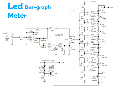
Several LED above and other components used to determine the signal amplifier, when in a state of high and low . If the signal received from the amplifier circuit is high then the LED lamp are lit up everything and more bright LED lamps, but otherwise if the received signal is low then the lights on only one or two , even absent or faint. To use the circuit you can connec with the output amplifier or speaker output , if there is reinforcing the other in the amplifier , can be connected to the output.

Stereo Power Amplifier Using IC 7905

Image
79xx is a widely known series of low-cost, fixed-negative-voltage regulators. These integrated circuits are available with output current of 100-150 mA (L series), 0.4-0.5A (M series), up to 1A (standard series), etc. They can be used in many applications other than regulators, audio power amplifier being one of them.  As shown in the circuit diagram, a simple stereo audio amplifier is built around two 7905 negative-voltage regulators (IC1 and IC2) and a few discrete components. The 7905 IC (a -5V regulator) used here is readily available. However, the circuit will also work with other 79XX regulators if appropriate power supply is used. Both channels shown in the diagram are identical. Hence the description below is only for the first channel. The quality of the output signal is within acceptable limits.  Circuit diagram : Stereo Power Amplifier Circuit Diagram   Regulator IC 7905 works as an amplifier for the voltages applied to common pin2 (Ground or GND). The minimal voltage drop

Stereo Headphone Amplifier

Image
Stereo Headphone Amplifier circuit uses DC voltage source 9Volt. As the name suggests this headphone amplifier circuit has inpur stereo and output to power about 50mW at 32 Ohm load. The series of "Stereo Headphone Amplifier" It uses mini-amplifier IC NE5534. Because of this NE5534 IC didalamanya there are 2 pieces mini amplifier then simply use 1 piece of IC NE5534 to Stereo Amplifier aHeadphone this. Stereo Headphone Amplifier series has this capability and low distortion, low noise. Stereo Headphone Amplifier circuit has a strengthening of 3.5 with 3.6 Vpp at 32 Ohm load. Component Stereo Headphone Amplifier P1 = 22K R1 = 18K R2 = 68K R3 = 68K R4 = 68K R5 = 18K R6 = 68K C1 = 4.7uF/25v C2 = 4.7uF/25v C3 = 22pF C4 = 220uF/25v C5 = 220uF/25v C6 = 4.7uF/25v C7 = 22pF C8 = 220uF/25v J1 = 3.5mm Stereo Jack B1 = 9V Alkaline Battery IC1 = NE5532 or NE5534 SW1 = SPST Toggle Switch

Electra Distortion

Image

Ocean thermal energy conversion process

Image

Cheap And Cheerful Transistor Tester

Image
By using a simple visual indicating system, this small transistor tester allows you to run a quick ‘go/non-go’ check on NPN as well as PNP transistors. If the device under test is a working NPN then the green LED (D1) will flash, while the red counterpart will flash for a functional PNP device. However if the transistor is shorted, both LEDs will flash, and an open-circuit device will cause the LEDs to remain off. The circuit is based on just one CD4011B quad NAND gate IC, four passive parts and two LEDs. The fourth gate in the IC is not used and its inputs should be grounded. Alternatively, you may want to connect its inputs and output in parallel with IC1.C to increase its drive power to the transistor test circuit. IC1.A and IC1.B together with R2, R3 and C1 form an oscillator circuit that generates a low-frequency square wave at pin 4. This signal is applied to the emitter of the transistor under test as well as to inverter IC1.C. The inverted signal from IC1.C and the oscillator outp

Simple FM transmitter circuit

Image
Two transistor FM transmitter. Description.  A lot of FM transmitter circuits have been already published here. This just another one, a simple two transistor FM transmitter.The first stage of the circuit is a preamplifier stage based on transistor Q1. This is a collector to base biased amplifier stage where resistor R2 sets the collector current and R1 provided the necessary collector to base bias. C1 is the input DC decoupling capacitor which couples the input audio signal to the Q1 base. C8 is the power supply by-pass capacitor. Next stage is the oscillator cum modulator stage built around transistor Q2. Electrolytic capacitor C2 couples the output of the first stage to the second stage. R3 and R4 are the biasing resistors of Q2. R5 is the emitter resistor of Q2. Inductor L1 and trimmer capacitor C5 forms the tank circuit which is necessary for creating oscillations. The modulated FM signal is available at the collector of Q2 and it is coupled to the antenna using capacitor C9. Circ

Hot Water Level Indicator

Image
A simple device to indicate various levels of hot water in a tank, save fuel bills and the economy of the planet with this circuit. SW1 is a normally open press button switch which allows you to view the level of hot water in a hot water tank. When pressed the voltage difference at the junction of the thermistor and preset is compared to the fixed voltage on the op-amps non-inverting input. Depending on the heat of the water in the tank, the thermistors resistance will toggle the op-amp output to swing to almost full voltage supply and light the appropriate LED. Hot Water Level Indicator Schematic Construction: Masking tape was used to stick the bead thermistors to the tank. Wires were soldered and insulated at the thermistors ends. A plastic box was used to house the circuit. Battery life will probably be 4 to 5 years depending on how often you use the push switch, SW1. Sensor Placement: Thermistors NTC1-4 should be spread evenly over the height of the tank. I placed NTC1 roughly 4 in

H Bridge Motor Controller Circuit Diagram

Image
This circuit is a bidirectional H bridge that makes control of DC motors. The circuit is based on IC L298 IC from ST Microelectronics. The L298 is a dual bridge driver that has a wide range of operating voltage and can load up to 3A. The IC also features low saturation voltage and over temperature protection.   H Bridge Motor Controller Circuit Diagram   Do not connect a motor that consumes more than 2.5A of current. The main power source may be any voltage between 3 and 40V DC. Put LM298 with a heat sink properly.

USB FX2 USB 2 0 interface board circuit schematic

Image
USB-FX2 USB-2.0 interface board circuit schematic There are some things one should be aware of when building the design above: Resonator: According to the data sheet, the FX2LP has an on-chip oscillator circuit which requires an external 24MHz (±100ppm) parallel resonant, fundamental mode crystal with 500uW drive level and 12pF (5% tolerance) load capacitors. So, you can't just put any 24MHz crystal there but things don't seem to be as critical as one may expect. I'm using a 24MHz fundamental mode crystal (24-MA505 from Reichelt) with 10..15pF caps (or even 32pF). ( Note: In the schematic above, there are 2 crystal oscillators in parallel merely to have both options on the PCB (one of them is an SMD). Only one of them is actually soldered onto the board.) EEPROM: You can use an optional serial EEPROM to store either USB configuration data or a complete program which is loaded into the microcontroller's RAM at startup. You can leave it away completely to use defau

Surf Sound Synthesizer Circuit Diagram

Image
Many people who live close to the ocean have the benefit of being lulled to sleep by the sound of the surf. This circuit may provide a similar benefit to all those poor unfortunates who don’t live near the seaside but who do have the small consolation that they don’t have to worry about rust and corrosion in a salty atmosphere. The circuit consists of four unsynchronised oscillators which are mixed together to modulate a white noise source to simulate the more or less random nature of surf sounds. You won’t hear the waves crashing but the ebb and flow of the white noise will help mask other noises which would otherwise disturb your sleep. The four oscillators are based on four op amps in a TL074 or TL084 quad op amp package (IC1). IC1a, IC1b, IC1c & IC1d are configured as Schmitt trigger oscillators with their operating frequencies defined by the resistor connected between their outputs (pins 1, 7, 8 & 14) and the respective inverting inputs (pins 2, 6, 9 & 13), as well as

How to Flirt LEDs

Image
A major problem when working with LEDs, is particularly novices connecting the LED to the circuit, or how to calculate the value of resistance used. Currently LEDs are very efficient, common and therefore the current needed to illuminate them is quite low: 5mA or less for the LED indicators and 20mA for high brightness LEDs. LEDs are relatively tolerant stream so it can vary between 5mA and 15mA for LED common between 15mA and 30mA for LED high brightness. The formula for calculating the resistance is obtained by Ohm's law and is as follows: R = (V - V-LED) / I wherein: R = resistance V = voltage V-LED = LED voltage typical (varies according to whether the LED) I = current HI is the current through the LED For example, if we have a red LED connected to 12V with a current of 5mA: R = (12V - 1.2V) / 5mA = 2160 ohms (using default values ​​of resistance: 2.200 ohm) Calculation base resistors for High Brightness LEDs for voltage 12 Volts LED Blue and White Vled v 3.70 curre

600W Audio Amplifier

Image
POWER : Maximum Output power @ 8ohms : 300watt Absolute max power supply voltage :±38V to ±40V Recommended power supply voltage :±30V to ±35V GENERAL DISCRIPTION : The circuit is based around {LM4702}manufactured by NATIONAL semiconductors&{MJ11029-MJ11028} by ON semiconductors It is a high fidelity audio power amplifier. Designed for demanding consumer and pro-audio applications. You can also use this circuit with AV receivers, Audiophile power amps, Pro Audio High voltage industrial applications etc Amplifier output power maybe scaled by changing the supply voltage and number of output devices. The circuit includes thermal shutdown circuitry that activates when the die temperature exceeds 150°c. CIRCUIT’s mute function, when activated, mutes the input drive signal and forces the amplifier output to a quiescent state.

TOURCAB 715D AMP 700w Class D Amplifier and Pre amplifier Circuit Diagram WALDMAN MUSIC

Image
Waldman Music - TOURCAB 715D Amplifier Schematic CIRCUIT DIAGRAM [Click on the Diagrams to Magnify]

Bully FM radio signals

Image
Interfere with fm radio signal is fun, if you're bored or no work, you can do at home, where neighbors , at school , or even near the transmitter. With the circuit above you can interfere with the speech signal in condenser microphone , and the signal will be issued by the circuit will then be received by FM radio receiver and a voice that we remove it before going out mixed with the signals emitted by radio FM transmitter. Part List : R1  = 4K7 R2  = 2K2 C1  = 1n5 C2  = 47pF C3  = 33pF L1  = Nikelin wire coil with a diameter 0,8 mm and 5mm in diameter wound coil 10 x T1  = 2N3906 Mic= Condenser Microphone If the circuit does not work on the errors may occur : Installation of the opposite transistor , incorrect placement of components , less voltage, the voltage is too high , the microphone is broken, transistor is damaged , broken coil . Please note this circuit can work and receive FM radio reciver at distance of about 500 meters. And not to much use , because the radio will be a

Zero Crossing Detector Circuit

Image
Zero Crossing Detector circuit is basically an application of a comparator. In the article series Zero Crossing Detector with Op Amp is built using a comparator of an Op Amp IC741/351. The process of detection of this comparator is  0Volt input signal crossing point by making reference value at comparator 0Volt.  The output of the Zero Crossing Detector circuit with Op Amp is wave-shaped box that detection result of the crossroads of 0 volt input signal.

Understanding silicon circuits inside the ubiquitous 741 op amp

Image
The 741 op amp is one of the most famous and popular ICs[1] with hundreds of millions sold since its invention in 1968 by famous IC designer Dave Fullagar. In this article, I look at the silicon die for the 741, discuss how it works, and explain how circuits are built from silicon. [ ]

Simple Logic Probe Circuit

Image
Description  This simple logic probe has both LEDs on with no signal at the input but due to the nor gates connected to the probe, indicates correctly when a high or low signal is present. It also works correctly for pulse trains. Normally both LEDs are forward biased and therefore on, powered by the 12V supply. When a logic "high" is present at the probe, IC1a's output goes low sending IC1b's output high. This turns off LED1 but forward-biases (and turns on) LED2. Conversely, a logic "low" at the probe will send IC1b low, turning LED1 on and LED2 off.  Circuit Diagram: Source http://www.extremecircuits.net/2010/05/simple-logic-probe.html

A Simple MD Catridge Preamplifier

Image
Phonographs are gradually becoming a rarity. Most of them have had to yield to more advanced systems, such as CD players and recorders or (portable) MiniDisc player/recorders. This trend is recognized by manufacturers of audio installations, which means that the traditional phono input is missing on increasingly more systems. Hi-fi enthusiasts who want make digital versions of their existing collections of phonograph records on a CD or MD, discover that it is no longer possible to connect a phonograph to the system. Circuit diagram : A Simple MD Catridge Preamplifier Circuit Diagram However, with a limited amount of circuitry, it is possible to adapt the line input of a modern amplifier or recorder so that it can handle the low-level signals generated by the magnetodynamic cartridge of a phonograph. Of course, the circuit has to provide the well-known RIAA correction that must be used with these cartridges. The preamplifier shown here performs the job using only one opamp, four resisto

Solar Hot Water Panel Differential Pump Controller

Image
This circuit optimises the circulation of heated water from solar hot water panels to a storage cylinder. It achieves this by controlling a 12V DC pump, which is switched on at a preset temperature differential of 8°C and off at about 4°C. This method of control has distinct advantages over some systems that run the pump until the differential approaches 0°C. In such systems, the pump typically runs whenever the sun shines. A small 10W solar panel charging a 12V SLA battery is sufficient to run the controller. Most commercial designs use 230VAC pumps, which of course don’t work when there is a power outage or there is no AC power at the site.   Operation: Temperature sensors TS1 & TS2 are positioned to measure the highest and lowest water temperatures, with one at the panel outlet and the other at the base of the storage cylinder. The difference between the sensor outputs is amplified by op amp IC1d, which is configured for a voltage gain of about 47. As the sensors produce 10mV/°C

How to wire up a Stomp Box Effects Pedal

Image
Today we're going to talk about how to wire up a stompbox. Apart from the effects circuit itself, there are three things that have to be thought about when wiring up a stompbox, which are the stomp switch, the stereo input jack and the DC-in connector. I’ll be referring to this image throughout the explanation (as with all images on here, click to enlarge): 1. The Switch To try to make this easy to follow, consider the left-hand column of the switch to be the input column, the middle column to be the LED column, and the right-hand column to be the output column. If for any reason you only have a 6-pin switch, you can still use it, just without the LED column. Off position In the OFF position, pin 4 is connected to pin 7, pin 5 is connected to pin 8, and pin 6 is connected to pin 9 (in my diagram at least – you may have a switch with different numbers written on it, though often they have none at all). Looking at just the left and right columns, the input comes in from the input jac

1 – 9V Variable Desktop Power Supply

Image
Here the variable desktop power supply which will convert a high input voltage (12V) from the SMPS / PSU of a desktop computer into small output voltage (1.25 to 9 volts). This converter will be very beneficial for electronics hobbyists. An adjustable three-pin voltage regulator chip LM317T (IC1) is applied right here to deliver the desired voltages. The LM317T regulator, in TO-220 pack, could deal with current of approximately 1 ampere in reality.                                          Above schematic diagram is the circuit of the variable desktop power supply. Regulator IC LM317T is set up in its standard application. Diode D1 protects against polarity reversal and capacitor C1 is an additional buffer. The green LED (LED1) signifies the status of the power input. Diode D2 keeps the output voltage from increasing above the input voltage when a capacitive or inductive load is hooked up at the output. Similarly, capacitor C3 eliminates any residual ripple. Connect a common digital vol

Simple and extensible microprocessor driver for robots

Image
I will start from saying that the board could be replaced by any Arduino plus some(s) its motor driver shield(s). So why I made it you may ask? Well, while I made this tiny tank-robot model presented on below pictures, I wanted to make at least some things by myself, and decide what I need and how I need it instead of only buying prefabricated stuff. [ ]

Failure is the pillar of success

Image
Some of the unsuccessful circuits in the early stage of SMPS learning During the last five years of my venture in SMPS circuits, I had failed many hundred times trying to design successful SMPS circuits. Since I am not institutionally trained, most of my circuits were based on test and trial, taking help from books, internet, forums, application notes, datasheets, etc. Hundreds of hours of failure could not deter me from relentless pursuit to learn - rather, taking lessons from these failures, I moved forward. Now, I am somewhat confident that I learnt a little bit of SMPS and can venture in SMPS circuits confidently.

MAX1573 White LED Driver Schematic

Image
This white LED driver electronic project circuit is designed using the MAX1573 integrated circuit , manufactured by Maxim Semiconductor.This white led driver circuit circuit drives as many as four white LEDs in parallel from a 3.3V source, and adjusts the total LED current from 1mA to 106mA, in 64 steps of 1dB each .To control the LED brightness, op amp U2 monitors the difference between the high-side voltage and the wiper voltage of digital potentiometer U1. The op amp then multiplies that voltage by a gain to set the maximum output current. Zero resistance at the pot's W1 terminal corresponds to minimum LED current, and therefore minimum brightness. Because the SET voltage is fixed (at 0.6V), any voltage change at the left side of R5 changes ISET, and the resulting change in LED currents changes their brightness level. R5 sets the maximum LED current: R5 = 215x0.6/ILED(Desired) (ILED is the current through one LED) .U1 integrated circuit is a digital potentiometer with logarithmi

Ultra Low Drop Linear Regulator

Image
The circuit is a MOSFET based linear voltage regulator with a voltage drop of as low as 60 mV at 1 ampere. Drop of a fewer millivolts is possible with better MOSFET s having lower  RDS(on)  resistance.  The circuit in Fig.1 uses 15V-0-15V secondary output from a step-down transformer and employs an n-channel MOSFET IRF540 to get the regulated 12V output from DC input, which could be as low as 12.06V. The gate drive voltage required for the MOSFET is generated using a voltage doubler circuit consisting of diodes D1 and D2 and capacitors C1 and C4. To turn the MOSFET fully on, the gate terminal should be around 10V above the source terminal which is connected to the output here. The voltage doubler feeds this voltage to the gate through resistor R1. Adjustable shunt regulator TL431 (IC2) is used here as an error amplifier, and it dynamically adjusts the gate voltage to maintain the regulation at the output.  . Ultra Low Drop Linear Regulator Circuit Diagram   . Circuit Fig.1 With ade

Low Impedance Microphone Amplifier

Image
The circuit is a microphone amplifier for use with low impedance (~200 ohm) microphones. It will work with stabilized voltages between 6-30VDC. If you don't build the impedance adapter part with T1, you get a micamp for higher impedance microphones. In this case, you should directly connect the signal to C7. R1=15k R2= 150k R3= 2k2 R4= 820 R6= 10k R7= 10k P1= 1M C1= 3k9 C2= 100u C3= 22u C4= 4u7 C5= 470u C6= 10u C7= 100n C8= 47u UNIPOLAR D1= 1N4148 U1= TL081 CN1= SIL6

Schematic Audio Power Amplifier with IC TDA2822

Image
TDA2822 is manufactered by PHILIPS , its based on this amplifier . Minimum voltage 3 volts and maximum voltage 15 volts. Power output 2 x 1,8 stereo with 4 Ohm impedance. Quiescent current 6 mA , sensitive input is 30 Hz to 18 kHz. See circuit diagram below :

Temperature Candle Using LED

Image
LED based projects require a lot of skill and hence only experienced circuit designers try out these circuits. But there are also a few circuits in this genre that can be done by amateur electronic hobbyists. The temperature candle is one such circuit. Read on to know more about this. The hardware components that are required to build this circuit are listed below: Microcontroller Temperature Sensor RGB LED PCB The circuit design is pretty simple. The LED is made to flicker by the microcontroller and the color is based on the ambient temperature at that point. The temperature of the room can be known by observing the color of the LED. The temperature value is obtained in degree Celsius. This value is received as a result of pressing the reset button on the PCB. This value can also be obtained by providing power to the device. Once the device is powered up, the change in temperature is indicated. The blue LED is triggered for a temperature increase of 10 degrees. The red LED is trig

Cheap 12V to 220V Inverter

Image
Even though today’s electrical appliances are increasingly often self-powered, especially the portable ones you carry around when camping or holidaying in summer, you do still sometimes need a source of 230 V AC - and while we’re about it, why not at a frequency close to that of the mains? As long as the power required from such a source remains relatively low - here we’ve chosen 30 VA - it’s very easy to build an inverter with simple, cheap components that many electronics hobbyists may even already have. Though it is possible to build a more powerful circuit, the complexity caused by the very heavy currents to be handled on the low-voltage side leads to circuits that would be out of place in this summer issue. Let’s not forget, for example, that just to get a meager 1 amp at 230 VAC, the battery primary side would have to handle more than 20 ADC!. The circuit diagram of our project is easy to follow. A classic 555 timer chip, identified as IC1, is configured as an astable multivibr

5V 10A output switching power supply

Image
The Schematic above shows a 10A power suplly with a 5V output and with power 50W. It is a flyback converter operating in the continuous mode. The circuit features a primary side and secondary side controller with full protection from fault conditions such as overcurrent. After the fault condition has been removed the power supply will enter the soft start cycle before recomming normal operation. Component Values : Resistor R1_____100Ω R2_____1Ω 1W R3_____10Ω R4_____100KΩ R5_____0.33Ω 1W R6_____10KΩ R7_____390Ω R8_____22KΩ R9_____68Ω R10____10Ω R11____3.3Ω RL_____5Ω 10W Capacitor C1_____0.022uF 400V C2_____470uF  250V C3_____470uF C4_____220pF C5_____470pF C6_____2200pF C7_____270pF C8_____39pF C9_____11,000uF C10____10uF C11____0.047uF Diode D1____1N4937 D2____MBR1035 M1____Diode Bridge Inductor , Transformator L1_____25uH T1_____Lp - 9 mH = 1 : 15 T2_____50 uH. n = 1: 3 Transistor Q1____BUZ80A Q2____GE IRF823