Posts

Showing posts from March, 2017

High Power Audio Amplifier 2800W Circuit Schematic Diagram

Image
Description Mono high power amplifier is actually a powerful 1400 W, but if this hihgh power amplifier circuit is doubled and you want to create stereo, high power amplifier the necessary components and pcb requires two-fold. So if the stereo high power amplifier 2 X 1400W. Schematic Circuit diagram is still less by looking at the circuit that was so below, the finished circuit has been added with a gains using JRC4558 IC by the two and the picture ic where it can be seen below. For circuit buffers, drivers , and booster use multiple transistors and other components (can be seen listed component ). And high power amplifier project that is so below is just part of the buffer and driver while the booster has not been made​​. For additional transistors in the booster or high power amplifier end scheme can be found Booster output power amplifier. Circuit Schematic Diagram : Part List : R1_____560Ω R2_____100Ω R3_____2K2Ω R4_____560Ω R5_____1Ω R6_____27KΩ R7_____10KΩ R8_____100Ω R9___

125MHz Dev Board with an ARM Cortex M3

Image
The Simplecortex is a microcontroller development board that is shield compatible with the Arduino. The Simplecortex has a fast microcontroller, the LPC1769 from NXP. This is a ARM Cortex M3 microcontroller with 512KB flash, 64KB RAM and it runs at 120Mhz. To make sure that the Simplecortex is easy to use we made tutorials for almost every peripheral on the chip and examples to get you started. There are tutorials for simple stuff like IO control up to more advanced tutorials for MicroSD cards. If you have ideas for a new tutorial or made a tutorial yourself, feel free to drop an email or post it in the forum. The Simplecortex also has an onboard debugger. It can also be used to program external devices like a self made PCB for your own project. No more microcontrollers with pre-programmed bootloader needed.        [ ]

Crowbar Speaker Protection Circuit Diagram

Image
This is the Crowbar Speaker Protection Circuit Diagram. Crowbar circuits are so-called because their operation is the equivalent of dropping a crowbar (large steel digging implement) across the terminals. It is only ever used as a last resort, and can only be used where the attached circuit is properly fused or incorporates other protective measures. A crowbar circuit is potentially destructive - if the circuitry only has a minor fault, it will be a major fault by the time a crowbar has done its job. It is not uncommon for the crowbar circuit to be destroyed as well - the purpose is to protect the device(s) attached to the circuit - in this case, a loudspeaker. Description There's really nothing to it. A resistor / capacitor circuit isolates the trigger circuit from normal AC signals. Should there be enough DC to activate the DIAC trigger, the cap is discharged into the gate of the TRIAC, which instantly turns on ... hard. A TRIAC has two basic states, on and off. The in-between s

Blown Fuse Monitor Circuit

Image
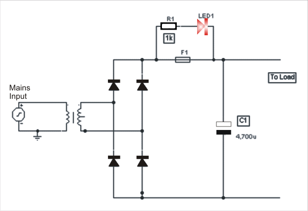
The post explains a simple fuse monitor or indicator circuit, for indicating the fuse status anytime. This is one of the simplest yet effective alarm cum monitor for detecting any blown fuse. A resistance of value 1K is placed in series with a LED and connected across the fuse which is to be tested. Normally when the fuse is healthy, LED 1 will not get any bias. Thus, it will not raise an alarm. However, the moment the fuse is blown , LED1 gets a feed in bias and starts to glow. The value of the resistor R1 and its wattage should obviously be decided depending on the type of LED and the supply across it. Suitably connecting a 12V zener and a 12V electronic buzzer across the fuse can enable an audio output (alarm sound) if so required.

Speech Filter

Image
In communications receivers and microphone amplifiers for transmitting equipment, there is frequently a need for a narrow, low-frequency band-pass filter that lets only the voice band through. This band is usually defined to be the portion of the audio frequency spectrum between approximately 300 Hz and 3300 Hz. In order to implement such a filter, we have calculated the values for two fifth-order Butterworth filters having these corner frequencies and connected them in series. The result is a band-pass filter for the desired pass-band with a skirt steepness of 100 dB/decade.  The first opamp (IC1) acts as a buffer. Speech Filter Image :   The circuit can be powered by a unipolar supply voltage between 5 V and 18 V, which is a broad enough range that it should always be possible to find a suitable voltage when building the filter into existing equipment. The current consumption of the filter is only a few milliampères, which should rarely pose a problem. There is fairly wide selectio

Timer with Musical Alarm Circuit Diagram

Image
The timer with Musical Alarm  use famous CMOS oscillator/divider IC (IC1 ). Although this circuit operates in 9V its standby current drain is very low. The time delay of timer circuit can be adjusted by adjusting the preset VR1. The base of npn transistor T1 is connected to pin 3 of IC1 through resistor R4 and its emitter terminal is connected with pin 2 of melody generator IC­ (IC2) in order to provide positive supply when adjusted time delay is over. Timer with Musical Alarm Circuit Diagram Here the zener diode ZD1 is used as regulator which reduce power supply to required for operation of IC2 i.e. 3.3V. Lastly for music output the output from pin 1 of IC2 is fed to loud speaker via driver transistor and its volume is controlled by preset VR2. For starting the timer power is supplied by pressing switch SW1. Parts list Resistor (all ¼-watt, ±5%) R1 = 1.2 MΩ R2 = 2.2 MΩ R3 = 56 KΩ R4, R5, R6 = 1 KΩ VR1 = 1 MΩ VR2 = 1 KΩ Capacitors C1 = 0.01 µF C2 = 0.22 µF C3 = 1 µF/25V Semiconductor

10 Minutes Timer Using 555 Timer IC

Image
Applications of 555 timer IC is very diverse, one series of 10 Minute Timer with IC 555. 10 Minute Timer This circuit uses IC NE555 is set as a monostable multivibrator.  The timing of the timer circuit 10 minutes with the IC 555 is governed by the configuration of C2, R4 and R5. The greater the value of C2 at 10-minute timer circuit with IC 555 timer is active then the time will stay longer. Total resistance value between R4 and R5 also determine the active circuit 10 minute timer with IC 555, where the greater the value the longer time was also active. 10 Minutes Timer Using 555 Timer IC Circuit  Schematic The core active setting the timer on the set of C2 charging time for 10 minutes on the timer circuit with IC 555. So, with the value of C2 remain so with time on the circuit timing Timer 10 minutes by IC 555 can be set by changing the resistance value R 4 + R 5. Indicators of active timer at 10 minute timer circuit with IC 555 uses the LED D2 and D3 will light up only one course to

12V Inverter Circuit Using 4013

Image
This circuit is a circuit diagram 12V inverter is very easy to build, cheap components that many electronics hobbyists may even already have. Though it is possible to build a more powerful circuit, the complexity caused by the very heavy currents to be handled on the low-voltage side leads to circuits. The circuit diagram of 12v inverter is easy to follow. A classic 555 timer chip, identified as IC1, is configured as an astable multivibrator at a frequency close to 100 Hz, which can be adjusted accurately by means of potentiometer P1. It is used to drive a D type flip-flop produced using a CMOS type 4013 IC. This produces perfect complementary squarewave signals (in antiphase) on its Q and Q outputs suitable for driving the output power transistors. The following is a schematic drawing:   As the output current available from the CMOS 4013 is very small, Darlington power transistors are used to arrive at the necessary output current. We have chosen MJ3001s from the now defunct Motorola

Valve Sound Converter Circuit Diagram

Image
‘Valve sound’ is not just an anachronism: there are those who remain ardent lovers of the quality of sound produced by a valve amplifier. However, not everyone is inclined to splash out on an expensive valve output stage or complete amplifier with a comparatively low power output. Also, for all their aesthetic qualities, modern valve amplifiers burn up (in the full sense of the word!) quite a few watts even at normal listening volume, and so are not exactly environmentally harmless. This valve sound converter offers a cunning way out of this dilemma. It is a low cost unit that can be easily slipped into the audio chain at a suitable point and it only consumes a modest amount of energy. A valve sound converter can be constructed using a common-or-garden small-signal amplifier using a readily-available triode. Compared to using a pentode, this simplifies the circuit and, thanks to its less linear characteristic, offers even more valve sound. For stereo use a double triode is ideal. Beca

Room Noise Detector Schematic Circuit

Image
This circuit is intended to signal, through a flashing LED, the exceeding of a fixed threshold in room noise, chosen from three fixed levels, namely 50, 70 & 85 dB. Two Op-amps provide the necessary circuit gain for sounds picked-up by a miniature electret microphone to drive a LED. With SW1 in the first position the circuit is off. Second, third and fourth positions power the circuit and set the input sensitivity threshold to 85, 70 & 50 dB respectively. Current drawing is 1mA with LED off and 12-15mA when the LED is steady on. Circuit diagram : Room Noise Detector Circuit diagram Parts List : R1____________10K 1/4W Resistor R2,R3_________22K 1/4W Resistors R4___________100K 1/4W Resistor R5,R9,R10_____56K 1/4W Resistors R6_____________5K6 1/4W Resistor R7___________560R 1/4W Resistor R8_____________2K2 1/4W Resistor R11____________1K 1/4W Resistor R12___________33K 1/4W Resistor R13__________330R 1/4W Resistor C1___________100nF 63V Polyester Capacitor C2____________10µF 25V

How to use MQ2 Gas Sensor – Arduino Tutorial

Image
The MQ series of gas sensors use a small heater inside with an electro-chemical sensor. They are sensitive for a range of gasses and are used indoors at room temperature. The output is an analog signal and can be read with an analog input of the Arduino. The MQ-2 Gas Sensor module is useful for gas leakage detecting in home and industry. It can detect LPG, i-butane, propane, methane ,alcohol, hydrogen and smoke. Some modules have a built-in variable resistor to adjust the sensitivity of the sensor. [ ]

Auto Turn Off Alarm With 8 Minute Delay

Image
Here is a very simple   auto turn-off alarm with 8-minute delay circuit. This circuit uses a NE555 timer and CD4020B. When +12 Vdc is applied to the circuit, the output of IC2 is set low via C2, which turns on the relay, and IC1, a pulse generator. Auto Turn-Off Alarm With 8-Minute Delay Circuit Diagram:      IC1 pulses counter IC2. After 8192 clocks, IC2 output (pin 3) goes high, cuts off Q2, and completes the cycle.

Uninterruptible Power Supply with PIC17C43 Microcontroller

Image
This is a MicroChip Uninterruptible Power Supply (UPS) reference design with PIC17C43 microcontroller. The document is available to download from the end of this post. At times, power from a wall socket is neither clean nor uninterruptible. Many abnormalities such as blackouts, brownouts, spikes, surges, and noise can occur. Under the best conditions, power interruptions can be an inconvenience. At their worst, they can cause loss of data in computer systems or damage to electronic equipment. It is the function of an Uninterruptible Power Supply (UPS) to act as a buffer and provide clean, reliable power to vulnerable electronic equipment. The basic concept of a UPS is to store energy during normal operation (through battery charging) and release energy (through DC to AC conversion) during a power failure. UPS systems are traditionally designed using analog components. Today these systems can integrate a microcontroller with AC sine wave generation, offering the many benefits. The PI

Automotive Electronic Circuit Project of USB Car Charger

Image
Build a low-cost and very simple Automotive Electronic Circuit Project of USB car charger circuit diagram. This USB car charger circuit adapter from car cigar socket project is a DC DC power converter that safely converts the 12V car battery voltage into stable 5V. This circuit can be used to supply power from a car cigar lighter socket to a portable device that require a 5 volts.  USB Car Charger Circuit Diagram: This circuit makes it possible to power/recharge any USB power-operated device, using in-dash board cigar lighter socket of your car. The DC supply available from the cigar lighter socket is fed to an adjustable, three-pin regulator LM317L (IC1). R1 and R2 resistors regulate the output of IC1 to steady 5V, which is available at the ‘A’ type female USB socket. Red LED1 indicates the output status and zener diode ZD1 acts as a protector against high voltage. As you can see in the circuit diagram, the circuit is very simple and requires just few common cheap components. Even  if

iPhone 6 concept shows thinner handset with touch sensitive home button and 12MP camera

Image
iPhone 6 concept shows thinner handset with touch-sensitive home button and 12MP camera Created by Arthur Reis, a budding designer who aspires to join the ranks of Jony Ive and Shin Nishibori someday, 3D renderings of the iPhone 6 imagine a handset that looks largely identical to iPhone 5 (think: anodised aluminium casing with chamfered edges), but an impressive 20 per cent slimmer at just 6.1mm thick. The handset also features a 12-megapixel camera with an ‘iSight Pro’ sensor boasting an f/1.8 aperture and a ‘Magic TrackPad’ that replaces the physical home button with a touch-sensitive equivalent. As far as we’re concerned, this is one of the best iPhone concepts we’ve seen, principally because it doesn’t go crazy on novel or unrealistic features as most concepts do. Apple is always trying to make its handsets slimmer, so a more slender iPhone is within the realms of possibility. And with Samsung upping the ante with a 13-megapixel camera on the freshly launched Galaxy S4, we can cert

Infrared Object Counter Circuit Diagram

Image
This infrared object counter can be installed at the entry gate to count the total number of people entering any venue. For example, it can be used at the railway stations or bus stands to count the people arriving per day or week. The counter uses an infrared transmitter-receiver pair and a simple, low-cost calculator. It works even in the presence of normal light. The maximum detection range is about 10 metres. That means the transmitter and the receiver are to be installed (at the opposite pillars of the gate) not more than 10 metres apart. No focusing lens is required. If an 8-digit calculator is used the counter can count up to 99,999,999 easily, and if a 10-digit calculator is used the counter can count up to 9,999,999,999.  Fig. 1: Transmitter circuit Powered by a 9V battery, the transmitter circuit (see Fig. 1) comprises IC 555 (IC1), which is wired as an astable multivibrator with a centre frequency of about 38 kHz, and two infrared light-emitting diodes (LEDs). The receiver c

Light Detector Using 555IC

Image
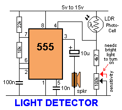
This circuit detects light falling on the Photo-cell (Light Dependent Resistor) to turn on the 555 and create a tone that is delivered to the speaker. Pin 4 must be held below 0.7v to turn the 555 off. Any voltage above 0.7v will activate the circuit. The adjustable sensitivity control is needed to set the level at which the circuit is activated.  Light Detector Circuit Diagram When the sensitivity pot is turned so that it has the lowest resistance (as shown in red), a large amount of light must be detected by the LDR for its resistance to be low. This produces a voltage-divider made up of the LDR and 4k7 resistor. As the resistance of the LDR decreases, the voltage across the 4k7 increases and the circuit is activated. When the sensitivity control is taken to the 0v rail, its resistance increases and this effectively adds resistance to the 4k7. The lower-part of the voltage-divider now has a larger resistance and this is in series with the LDR. Less light is needed on the LDR for it t

Power Diode For Solar Power Systems

Image
Apart from the sun, solar power systems cannot work without a reflow protection diode between the solar panel and the energy store. When current flows into the store, there is a potential drop across the diode which must be written off as a loss in energy. In the case of a Schottky diode, this is not less than 0.28 V at nominal current levels, but will rise with higher ones. It is clear that it is advantageous to keep the energy loss as small as possible and this may be achieved with external circuitry as shown in the diagram. The circuit is essentially an electronic switch consisting of a high precision operational amplifier, IC1a, a Type OP295 from Analog Devices, and a MOSFET, T1. This arrangement has the advantages over a Schottky diode that it has a lower threshold voltage and the lost energy is not dissipated as heat so that only a small heat sink is needed. When the potential at the non-inverting input of the op amp, which is configured as a comparator, rises above that at the i

High Performance Interruption Detector

Image
The circuit presented here detects interruption in security systems. Its features include no false triggering by external factors (such as sun-light and rain), easy relative positioning of the sensors and alignment of the circuit, high sensitivity, and reliability. The circuit comprises three sections, namely, transmitter, receiver, and power supply. The transmitter generates modulated IR signals and the receiver detects the change in IR intensity. Power supply provides regulated +5V to the transmitter and the receiver. The power supply and the speaker are kept inside the premises while the transmitter and the receiver are placed oppo site to each other at the entrance where the detection is needed. Three connections (Vcc, GND, and SPKR) are needed from the power supply/speaker to the receiver section, while only two connections (Vcc and GND) are required to the transmitter. The transmitter is basically an astable multivibrator configured around NE555 (IC3). Its frequency should match

11 W Stereo or 22 W Mono Power Amp

Image
Integrated AF power amps have seen great improvements in recent years offering improved power and easier use. The TDA1519C from Philips contains two power amplifiers providing 11 W per channel stereo or 22 W mono when the two channels are connected in a bridge configuration. The special in-line SIL9P package outline allows the chip to be conveniently bolted to a suitable heatsink. The TDA1519CSP is the SMD version, in this case the heat sink is mounted over, and in contact with, the top surface of the chip.  11W Stereo Amplifier Circuit Diagram The operating voltage of this device is from +6V to +17.5V. The two channels of the amplifier are different in that one channel, between pins 1 and 4, is a non-inverting amplifier, while the other between pins 9 and 6 is an inverting amplifier. It is therefore necessary in stereo operation, to wire the speakers so that one of them has its polarity reversed. Each amplifier has an input impedance of 60kΩ and a voltage gain of 40dB, i.e. 100 times.

Ceiling Fan Regulator Motor Speed Control Circuit Diagram

Image
This is a simple ceiling fan regulator circuit diagram. It is used to control the speed of a ceiling fan. In the other words it is an AC motor speed controller circuit, as because it's control the speed of a AC motor(Ceiling Fan).  This ceiling fan regulator circuit built with few numbers of parts. The circuit mainly  based on Z0607 TRIAC. This is a low power AC semiconductor device. Generally which is used to controlling speed of low power ac motor speed.  Circuit Diagram of Ceiling Fan Regulator :      In this ceiling fan regulator circuit , R1=500KΩ is a variable resistor that is used to adjust the fan speed. Capacitor C1 2A104J is a Polyester film capacitor. Pin Diagram of  TRIAC(T1)- Z0607:  Fig: Z0607-TRIAC Pin diagram Pin Diagram of Variable Resistor R1: Fig: Pin Diagram of Variable Resistor Parts List Ceiling Fan Motor Speed Controller circuit: T1 = Z0607 -TRIAC D1 = DB3 C312 -DIAC R1 = 500KΩ -Variable Resistor R2 = 37KΩ -Resistor C1 = 2A104J -Polyester film capacitor. M1

Tone Burst Generator

Image
This is simple Electronic Circuit Diagram of Tone Burst Generator Circuit. Integrated circuit gates ICl-a and TCl-b form a monostable, whose time constant is determined by C2 and R3. When the transmitter is dekeyed (and then almost immediately rekeyed) point TX+ goes low and takes pin 1 low for a short time. This triggers the start of the timing period controlled by C2/R3. The capacitor C2, charges via R3 until the trigger point of gate ICl-b is reached. At this point, the monostable changes state and pin3 goes low again. On the prototype, this time was about 700 ms. The pulse occurs each time after dekeying and it is normally inaudible. Tone Burst Generator Circuit Diagram: If, however, point TX+ goes high again (as in immediate rekeying) the monostable is still in the enabled state and the oscillations of ICl-c are present in the transmission. During this time period, the buffer gate, ICl-d, is enabled and the tone is therefore passed to the output.

Simple Capacitance operated battery powered light Circuit Diagram

Image
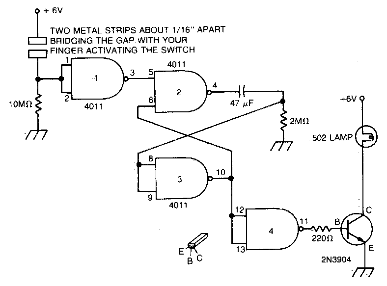
This is the Simple Capacitance operated battery powered light Circuit Diagram. In this simple project Touch the plate and the light will go on and constant of the 47 µf capacitor and the 2M remain on for a time determined by the time resistor. Simple Capacitance operated battery powered light Circuit Diagram Sourced By: Circuitsproject

F V Converter With Sample And Hold Circuit Diagram

Image
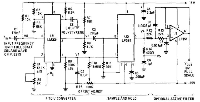
This is the simple Frequency/Voltage Converter With Sample And Hold Circuit Diagram. U1 is a frequency/voltage converter, feeding sample-and-hold circuit using an LF381. An LF351 provides 10-V M-scale output. The circuit produces 1-V/kHz output. F-V Converter With Sample And Hold Circuit Diagram

FM Radio Transmitter schematic with pcb

Image
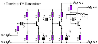
For those of you like / love to talk in the air can assemble this simple circuit that can be received by the radio receiver to within a few hundred feet. The voice that issues by this circuit at all clear without rustling. Can also be used to link communications over the air using this radio transmitter, provided that other person also had the same circuit. This PCB design : Description : Resistor R1__________________1K R2__________________18K R3__________________82K R4__________________1K2 R5__________________5K6 R6__________________39K R7__________________18K R8__________________68K R9__________________470R R10_________________100R R11_________________50K XTal Q1__________________ Crystal according to the desired frequency Inductor L1__________________10uH Capacitor C1__________________10uF C2__________________30uF C3__________________20uF C4__________________47uF Transistor Tr1_________________2SB175 Tr2_________________2SB175 Tr3_________________2SB178 Antenna X1-1________________

RF power amplifier IC

Image
RF power amplifier IC is a type of electronic amplifier used to convert low-power radio frequency signal into a larger signal strength is important, usually for driving a transmitting antenna. This is usually optimized for high-efficiency, high output power (P1dB) of compression, loss of income on the input and output, better benefits, and optimal heat dissipation. RF power amplifier IC To make our amplifiers can also use transistors or IC OP Amp. In the op amp is actually a transistor that is in the form of a series so it's easier to use. Suppose that is used in the amplifier IC Op Amp 741 is a monolithic high performance electronic components that use Fairchild epitacial process. IC Op Amp 741 is an IC in which packed a differential circuit. The data sheet of IC Op Amp 741.

TDA2005 Audio Amplifier 2x10w

Image
TDA2005 description: The TDA2005 is a class B dual audio power amplifier in Multiwatt11 package specifically designed for car radio applications. Power booster amplifiers can be easily designed  using this device that provides a high current  capability (up to 3.5 A) and can drive very low  impedance loads (down to 1.6  in stereo  applications) obtaining an output power of more than 20 W (bridge configuration).  TDA2005 Audio Amplifier 2x10w TDA2005 features: High output power: Po = 10 + 10 W @ RL = 2 , THD = 10 % Po = 20 W @ RL = 4 , THD = 10 %. Protection against: Output DC and AC short circuit to ground Overrating chip temperature Load dump voltage surge Fortuitous open ground Very inductive loads Loudspeaker protection during short circuit for one wire to ground TDA2005 circuit diagram: TDA2005 Audio Amplifier 2x10w TDA2005 layout: PCB TDA2005 Audio Amplifier 2x10w Layout TDA2005 Audio Amplifier 2x10w

Simple FAN 7710 Ballast Control

Image
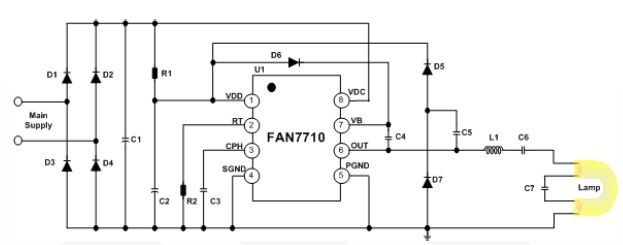
Using the FAN 7710 Ballast Control IC for Compact Fluorescent Lamps developed using Fairchild’s unique highvoltage process and system-in-package (SiP) concept can be designed a very simple low cost fluorescent lamp driver electronic project .The FAN7710 ballast control controls internal high-voltage stress and delivers 20W to the lamp at 320VDC voltage. FAN7710 ballast control incorporates a preheating /ignition function, controlled by an user-selected external capacitor, to increase lamp life. The FAN7710 detects switch operation from after ignition-mode through an internal active Zero-Voltage Switching (ZVS) control circuit.  Simple FAN 7710 Ballast Control Circuit Diagram The AC line input voltage (230 VAC 50 Hz) is rectified to provide a bus voltage of approximately 320 volts DC. Startup resistor R1 supplies initial power to the FAN7710 IC.The IC begins to oscillate and the charge pump circuit consisting of C2, D2 and D7 supplies the current to the VDD pin, which gets regulated thr

Canonical Ubuntu Edge smartphone sets new crowdfunding pledge record

Image
  Setting a new record as the highest-earning fixed crowd funding campaign on Indiegogo, a total amount of $10,288,472 (approximately £6.6 million) has, thus far, been generated in pledges by London-based developer Canonical for its Ubuntu Edge smartphone. The money raised by the Canonical Ubuntu Edge smartphone in its Indeigogo crowdfunding campaign has surpassed the record set by the Pebble smartwatch last year. Pebble had raised a total of $10,266,845 in its crowdfunding campaign. However, with the Ubuntu Edge crowdfunding campaign scheduled to end on August 21, Canonical is far from its achieving its overall funding target of $32 million. If the developer fails to reach the funding goal, it will have to return all the money to the backers. In case Canonical is successful in achieving the funding target of its Ubuntu Edge smartphone campaign on the Indiegogo crowdfunding website, it plans to deliver 40,000 handsets to qualifying backers by May 2014. Noting that the public interest i

Simple Active ir Motion Detector Circuit Diagram

Image
To explore how different motion detectors operate.To successfully build and test an ambient-light-ignoring active IR motion detector. Background  There are a wide variety of motion detectors available currently. To allow a better understanding of motion detectors,the following section provides a detailed description of a few different types. Ultrasonic Motion Detectors Ultrasonic transducers can be used to detect motion in an area where there are not supposed to be any moving objects.This type of motion detector is most commonly used in burglar alarm systems since they are very effective in this application.  Figure 1 shows the operation of an ultrasonic motiondetector. There are tw1o transducers: one emits an ultrasonicwave and the other picks up reflections from the differentobjects in the area. The reflected waves arrive at the receiverin constant phase if none of the objects in the area are moving.If something moves, the received signal is shifted in phase.  A phase comparator dete

Binary Coded Decimal BCD Clock

Image
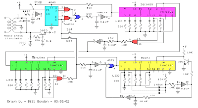
The clock circuit above uses seven ICs and 19 LEDs to indicate binary coded decimal time. The LEDs can be arranged (as shown in example above) so that each horizontal group of 3 or 4 LEDs represents a decimal digit between 0 and 9 and each individual LED represents a single bit or (binary digit) of the value. Binary digits have only two values (0 and 1) so a number written in binary would be something like 1001 or 0011, which represents decimal numbers 9 and 3 respectively. From right to left, each binary (1) represents increasing powers of 2, so that a 1 in the right hand place represents 2^0=1 and the next place to the left is 2^1=2 and then 2^2=4, and so forth. This makes binary counting fairly easy since each digit has a value of twice the one before or 1,2,4,8,16,32,64,etc. Thus the decimal value can be found by simply adding the values of each illuminated LED in the same row, (the total is shown in the box to the right). For example, the binary number 1001 would have a decimal v