Eighteen Watt Audio Amplifier
18 Watt Audio Amplifier circuit diagram . High Quality very simple unit No need for a preamplifier
.
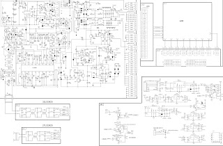
Circuit diagram :


.
Circuit diagram :
18Watt Audio Amplifier Circuit Diagram
Amplifier parts:
P1____22K Log. Potentiometer (Dual-gang for stereo)
R1___1K 1/4W Resistor
R2___4K7 1/4W Resistor
R3___100R 1/4W Resistor
R4___4K7 1/4W Resistor
R5___82K 1/4W Resistor
R6___10R 1/2W Resistor
R7___R22 4W Resistor (wirewound)
R8___1K 1/2W Trimmer Cermet (optional)
R2___4K7 1/4W Resistor
R3___100R 1/4W Resistor
R4___4K7 1/4W Resistor
R5___82K 1/4W Resistor
R6___10R 1/2W Resistor
R7___R22 4W Resistor (wirewound)
R8___1K 1/2W Trimmer Cermet (optional)
C1___470nF 63V Polyester Capacitor
C2,C5___100µF 3V Tantalum bead Capacitors
C3,C4___470µF 25V Electrolytic Capacitors
C6___100nF 63V Polyester Capacitor
C2,C5___100µF 3V Tantalum bead Capacitors
C3,C4___470µF 25V Electrolytic Capacitors
C6___100nF 63V Polyester Capacitor
D1___1N4148 75V 150mA Diode
IC1___TLE2141C Low noise, high voltage, high slew-rate Op-amp
Q1___BC182 50V 100mA NPN Transistor
Q2___BC212 50V 100mA PNP Transistor
Q3___TIP42A 60V 6A PNP Transistor
Q4___TIP41A 60V 6A NPN Transistor
Q2___BC212 50V 100mA PNP Transistor
Q3___TIP42A 60V 6A PNP Transistor
Q4___TIP41A 60V 6A NPN Transistor
J1___RCA audio input socket
Power supply :
18Watt Audio Amplifier Power Supply
Power supply parts:
R9___2K2 1/4W Resistor
C7,C8___4700µF 25V Electrolytic Capacitors
D2___100V 4A Diode bridge
D3___5mm. Red LED
D3___5mm. Red LED
T1___220V Primary, 15 + 15V Secondary, 50VA Mains transformer
PL1___Male Mains plug
SW1___SPST Mains switch
Notes:
- Can be directly connected to CD players, tuners and tape recorders.
- Do not exceed 23 + 23V supply.
- Q3 and Q4 must be mounted on heatsink.
- D1 must be in thermal contact with Q1.
- Quiescent current (best measured with an Avo-meter in series with Q3 Emitter) is not critical.
- Adjust R3 to read a current between 20 to 30 mA with no input signal.
- To facilitate quiescent current setting add R8 (optional).
- A correct grounding is very important to eliminate hum and ground loops. Connect to the same point the ground sides of J1, P1, C2, C3 & C4. Connect C6 to the output ground.
- Then connect separately the input and output grounds to the power supply ground.
Technical data:
Output power:
18 Watt RMS into 8 Ohm (1KHz sine wave)
Sensitivity:
150mV input for 18W output
Frequency response:
30Hz to 20KHz -1dB
Total harmonic distortion @ 1KHz:
0.1W 0.02% 1W 0.01% 5W 0.01% 10W 0.03%
Total harmonic distortion @10KHz:
0.1W 0.04% 1W 0.05% 5W 0.06% 10W 0.15%
Unconditionally stable on capacitive loads
Source : RedCircuits


Comments
Post a Comment